Gateway communications manual – AERCO XPC GATEWAY Communications User Manual
Page 52
GATEWAY COMMUNICATIONS MANUAL
52
Although it is recommended to utilize the AERCO BMS for boiler system control, a customer may opt to
utilize their own boiler system control system. If such is the case, the BMS/BMS II may be removed
entirely allowing the customer’s BAS/EMS system to interact directly (possibly using a protocol
translating XPC Communications Gateway device, if needed) with the C-More boiler controller. If the
BMS/BMS II is kept in the loop and Modbus Pass Thru is enabled, those control functions normally set by
the BMS/BMS II will continue to do so. All other control functions will now be facilitated by BAS/EMS
commands passed thru the BMS/BMS II directly to the C-More boiler controller.
If the BAS being utilized supports Modbus RTU protocol, it can be connected to the BMS either directly or
via a RS485-to-RS232 converter. However, if the BAS does not support Modbus protocol and utilizes
BACnet, N2 or LonWorks, the AERCO XPC Gateway must be used as described below.
1. Make the connections between the BMS and XPC Gateway as instructed in subsections 3.2.1.1 or
3.2.1.2.
2. Set up the C-More Boiler Controllers as described in Section 2, subsections 2.3 through 2.5.1.
3. Connect the C-More Boiler Controllers in a “Daisy-Chain” configuration.
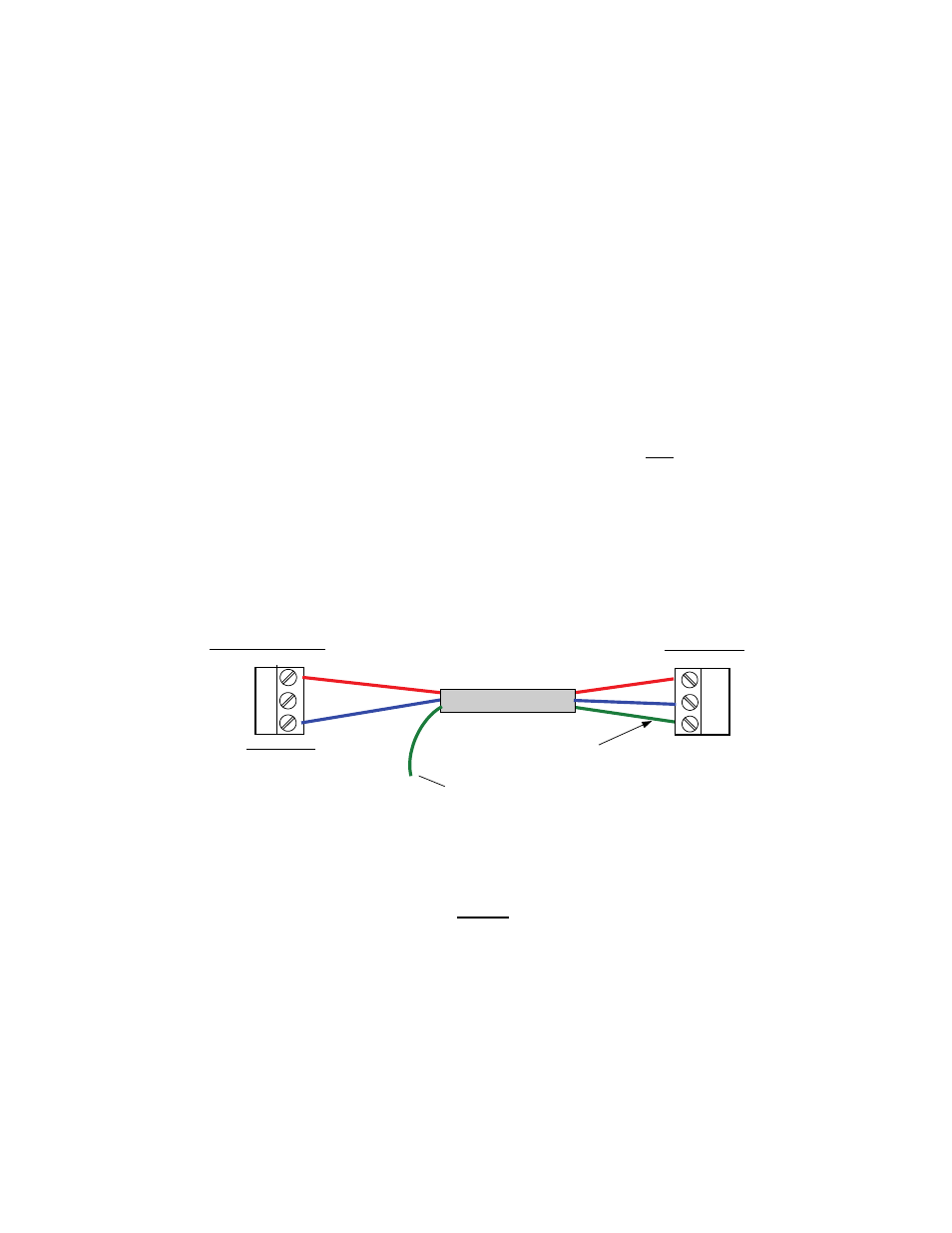
4. Refer to Figure 3-7 and connect the RS485 COMM terminals of the first C-More Boiler to the BMS
internal RS485 connector JP11 as follows:
(a)
(a) Connect the RS485 COMM + terminal to the +(B) terminal of JP11 in BMS.
(b) Connect the RS485 COMM - terminal to the -(A) terminal of JP11 in BMS.
(c) Terminate the shield at the BMS end only.
+
G
-
TERMINATE SHIELD
AT BMS ONLY
+ (B)
- (A)
SHLD
C-MORE I/O BOX
R
S
48
5 C
O
M
M
BMS RS485
JP11
FIRST UNIT
S
H
IE
L
D
TIE TOGETHER WITH
SHIELDS OF OTHER
C-MORE UNITS
RED (+)
BLUE
(-)
RED
(+)
BLUE (-)
Figure 3-7. BMS Connections to C-More Controller
NOTE
Refer to AERCO Instruction Manual GF-108M for additional information on
BMS keypad functions and displays.
5. With the BMS in the Field Adjust Mode, continue pressing the AIR TEMP key until MODBUS PASS
THRU
is displayed. Press the ▲ or ▼ arrow key until the second line of the display shows
ENABLED.
6. With PASS THRU set to ENABLED, both the BMS and the boilers can now be monitored.