1 bms wiring connections to xpc port 2, Gf-122 aerco xpc gateway, Figure 3-4. port 2 jumper settings – AERCO XPC GATEWAY Communications User Manual
Page 49: Figure 3-5. port 2 wiring connections for bms
GF-122 AERCO XPC GATEWAY
49
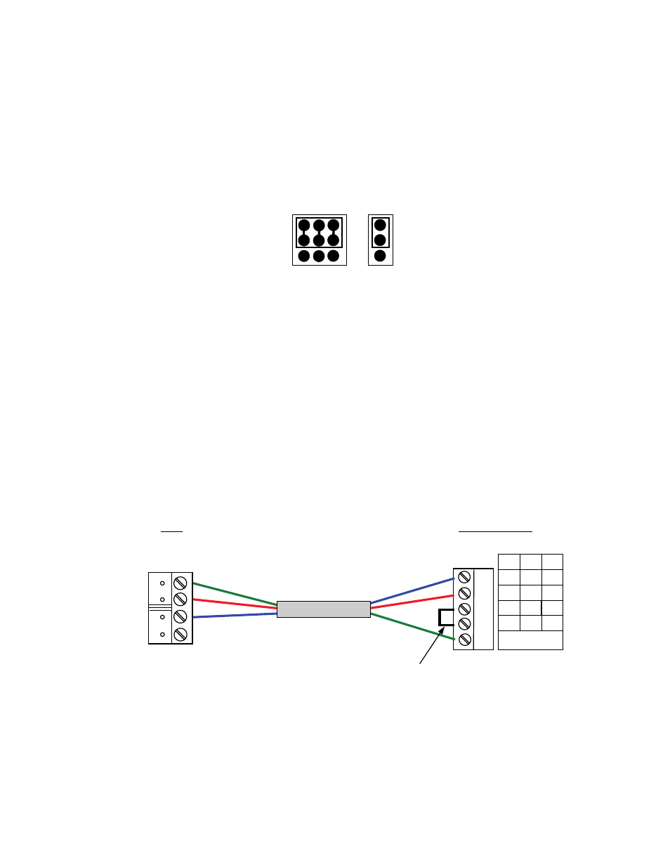
3.2.1.1 BMS Wiring Connections to XPC Port 2
When the BAS being used is communicating via BACnet MS/TP, Johnson N2 or LonWorks without an
SLTA, connect to XPC Port 2 as follows:
1. Position the XPC EIA-232/EIA-234 and 2W/4W jumpers to EIA-232 and 2W respectively as shown in
Figure 3-4.
EIA-485
EIA-232
2W
4W
Figure 3-4. Port 2 Jumper Settings
2. Refer to Figures 3-2 and 3-3 to locate the internal RS232 connector inside the wiring area of the
BMS.
3. At the BMS internal RS232 connector (JP12), refer to Figure 3-5 and connect the wire leads as
follows:
(a) Connect the TXD terminal of the BMS RS232 connector to Rx terminal on XPC Port 2.
(b) Connect the RXD terminal of the BMS RS232 connector to Tx terminal on XPC Port 2.
(c) Connect the GND terminal of the BMS RS232 connector to SIGNAL GROUND terminal on XPC
Port 2.
(d) Add a jumper between the DTR and DCD terminals on XPC Port 2. See Figure 1-3 (Detail B).
2W
4W
232
Net +
Net -
N/C
N/C
Tx +
Tx
Tx -
Rx
DTR
Rx - DCD
SIGNAL
GROUND
Rx +
Port 2
RED
BLU
E
GREE
N
(GND
)
RED
BLUE
GREEN
(GND
)
RXD
TXD
GND
RS232
JP12
XPC GATEWAY
BMS
JUMPER
Figure 3-5. Port 2 Wiring Connections for BMS
4. At the XPC Gateway, ensure that DIP switch 3 is set to the OFF (right) position.