1 multi-head mode, Controlling multi-head mode, Multi-head mode -2 – KEYENCE N-410 User Manual
Page 86: Controlling multi-head mode -2, Multi-head mode, Caution
5-2
Co
nt
5
5-1
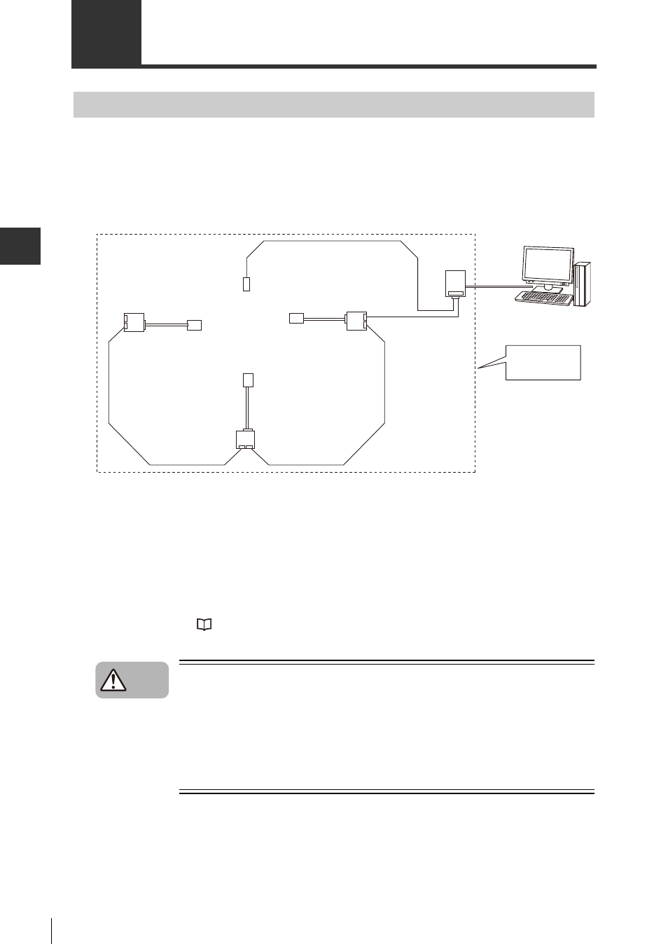
Multi-head Mode
Controlling Multi-head Mode
If you do not know where on a product the code is located, if there barcodes in multiple locations
or if the tag location on palletized shipping is variable, the code or tags cannot be read by a single
code reader or RF-ID. In these cases, multiple code readers will be needed to scan for barcodes
or IC chips in multiple locations or from multiple angles.
The N-410 can be used in multi-head mode in these cases to allow the host computer to control
multiple BL/SR/RF Series devices as one unit.
The N-410 can be controlled by the host computer in the following three ways.
• Data communication
Code data and tag access results are sent to the host computer.
• BL/SR/RF Series device command communication
Commands can be sent to BL/SR/RF Series devices.
• N-410 command communication
Allows direct control of the N-410 and allows N-410 settings to be changed.
Sending commands to the N-410 and to BL/SR/RF Series devices is the same as in multi-drop
link mode. Refer to
"4-1 Multi-drop Link Mode" (Page 4-2) for more information.
•
BL Series, SR Series, and RF Series devices cannot be mixed in multi-head
mode. Make sure that your networks are either exclusively BL/SR-Series
devices or exclusively RF Series devices when using multi-head mode.
•
When using the multi-drop link mode, the maximum number of characters
(number of data digits) that can be handled in a single communication is
992 (including additional data). Be careful with the number of data digits
when sending or receiving large size data such as an IC tag or 2D code.
N-R4
N-48
BL-U1
or
NX-50RS
Trigger Sensor
RS-485
RS-232C
N-410
BL/SR/RF Series
devices can be
used as one unit.
Caution