N-r4 – KEYENCE N-410 User Manual
Page 18
1-6
N-410 Overview
1
1-3
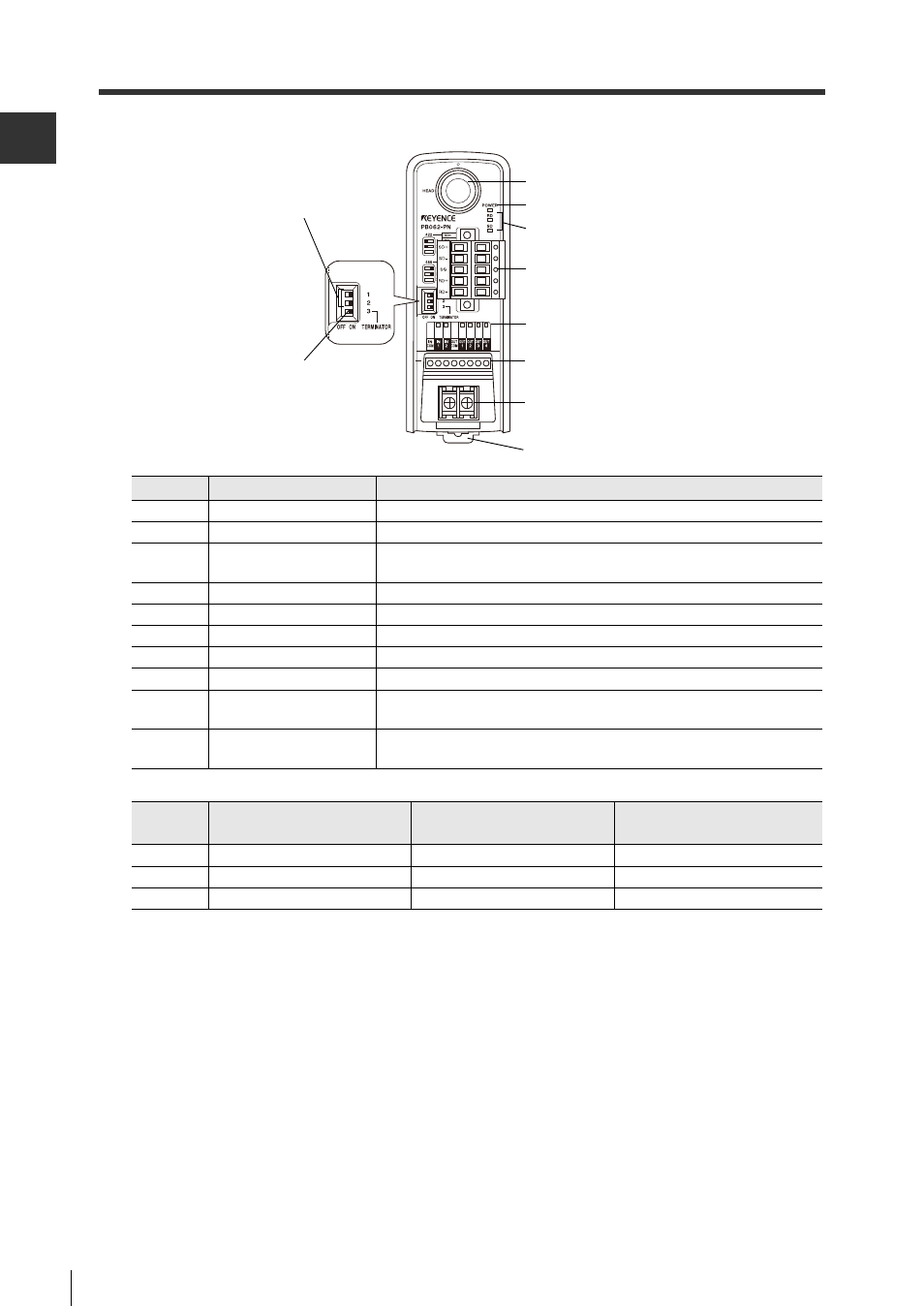
Part Names
N-R4
States of RS-422A/485 changeover switch and terminating resistance switch
* Factory settings are by default RS-485 communication and the terminating resistance set to the
OFF position.
Number
Name
Function
1
Head port
Used to connect the head.
2
Power LED
Lights when the power is ON.
3
Communication status
LED
Monitors the status of communication with the head.
4
RS-422A/485 connector Used to connect to the host (personal computer, PLC).
5
I/O status LED
Monitors the ON/OFF status of the I/O terminals.
6
I/O terminals
Used to connect I/O signal lines of control units.
7
Power terminal
Terminal for 24 V DC power supply input.
8
DIN rail mounting tab
Used to secure the N-R4 to a DIN rail.
9
RS-422A/485
changeover switch
Used to switch between RS-422A and 485 communications.
10
Terminating resistance
switch
Used to switch between ON and OFF for terminating resistance.
1. Head port
2. Power LED
4. RS-422A/485 connector
5. I/O status LED
6. I/O terminals
7. Power terminal
8. DIN rail mounting tab
9. RS-422A/485
changeover switch
3. Communication status LED
10.Terminating
resistance switch
Number
RS-422A
communication mode
RS-485
communication mode
Terminating
resistance ON
1
Left
Right
-
2
Left
Right
-
3
-
-
Right