3 part names, Part names -5, Part names – KEYENCE N-410 User Manual
Page 17: N-410
N-410 Overview
1
1-5
1-3
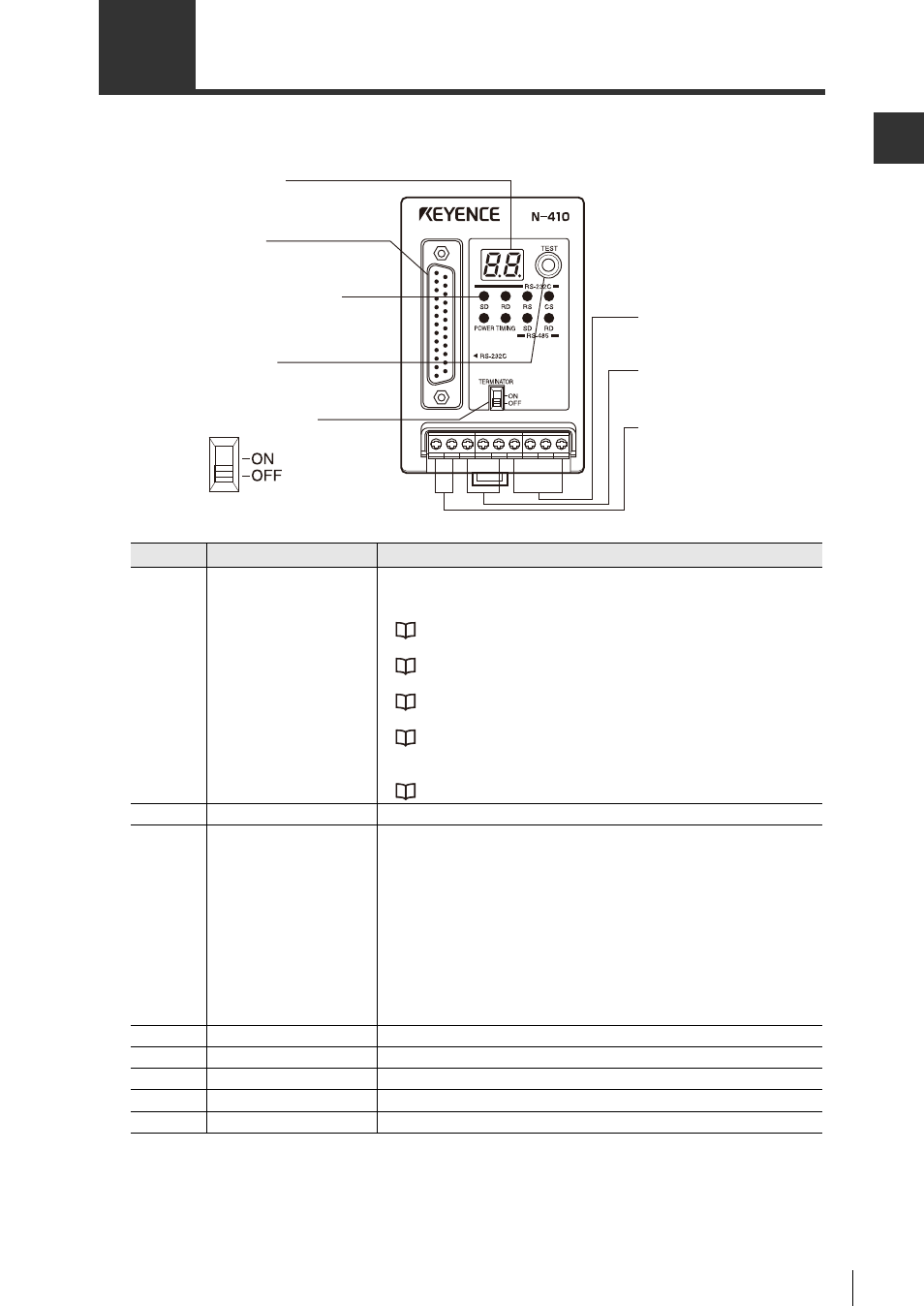
Part Names
N-410
Number
Name
Function
1
Display LED
• Normally displays the ID number of the N-410, which is 00.
• Displays the ID number of any device undergoing a connection
test
.
"2-7 How to Use the Connection Confirmation Test" (Page 2-31)
• Displays "55" during setting mode.
"4-5 N-410 Setting Commands" (Page 4-22)
• Displays "50" while initiating communications to change settings.
"3-2 Sending and Receiving Settings" (Page 3-9)
• Displays the error state of the N-410.
"Appendix 4 Main device display" (Page A-12)
• Displays the ID number of the currently communicating device
when sending hotline commands.
"Specifying the ID number to send commands to" (Page 4-20)
2
RS-232C
Connects the host computer to the PLC.
3
Communication state
display LEDs
• Power: Illuminates when power is on.
• Timing:Illuminates when the N-410 is receiving timing signals.
Illuminates when connected to a normal open point and is on.
Illuminates when connected to normal close point and is off.
(RS-232C)
SD, RD, RS, CS: Illuminates when there is communication over the
RS-232C port.
(RS-485)
SD: Illuminates when sending data
RD: Illuminates when receiving data
* When sending and receiving data, both SD and RD illuminate.
4
Test switch
Activates test switch mode.
5
Terminator switch
Toggles the terminator.
6
Power terminal
Connects a 24 V DC power source.
7
RS-485 terminal
Connects for multi-drop.
8
Trigger input jack
Used for trigger input in multi-head mode.
1. Display LED
6. Power terminal
7. RS-485 terminal
8. Trigger input terminal
2. RS-232C
3. Communication state
display LEDs
4. Test switch
5. Terminator switch