Bl-u1 dipswitch settings, Bl-u1 dipswitch settings -27, Pin layout for bl-u1 reader port – KEYENCE N-410 User Manual
Page 49
2-27
2-6
BL-U1 Connections and Wiring
Inst
allatio
2
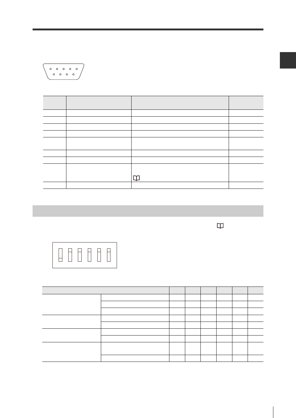
Pin layout for BL-U1 reader port
BL-U1 Dipswitch Settings
Set the interface to "RS-485 multi-drop" with the BL-U1 dipswitches. Refer to
485" (Page 2-30) for more information on "RS-485 Terminator."
Pin
number
Symbol
Explanation
Signal
direction
1
TIM
Trigger input
Output
2
RD (RXD)
Send RS-232C data
Output
3
SD (TXD)
Recieve RS-232C data
Input
4
OK
OK
Input
5
GND (SG)
Ground
(Common ground for all signals)
-
6
NG
NG
Input
7
RS (RTS)
RS-232C send capable
Input
8
CS (CTS)
RS-232C request send (controllable via
dipswitch)
"BL-U1 Dipswitch Settings" (Page 2-27)
Output
9
+5V
+5 V power source (1.5A)
Output
6 7 8 9
1 2 3 4 5
D-sub9 pin (male)
DCE specification (modem
definition)
#4-40screws (female)
Dipswitch number
1
2
3
4
5
6
Interface selection
RS-232C
ON
OFF
OFF
RS-422A
OFF
ON
OFF
RS-485 Multi-drop
OFF
OFF
ON
RS-422A Terminator
(100
)
OFF
OFF
ON
ON
RS-485 Terminator
(100
)
OFF
OFF
ON
ON
Select Reader port CS
control method
Reflects whether the RS-232 CS
is on or off
OFF
Usually on
ON
1
2
3
4
5
6
OFF
ON
*The diagram at the left
shows the factory settings.