Bl-u1 – KEYENCE N-410 User Manual
Page 20
1-8
N-410 Overview
1
1-3
Part Names
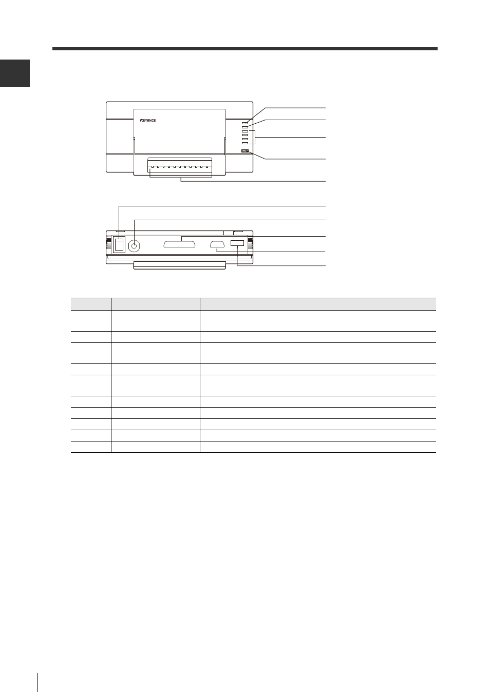
BL-U1
Number
Name
Function
1
OK/NG LED
•Illuminates green when output is OK.
•Illuminates red when output is NG.
2
Timing LED
Illuminates when trigger input is on.
3
Communication state
display LEDs
Monitors the state of communications at the RS-232C port.
From top to bottom: SD, RD, RS, CS
4
Power LED
Illuminates when power is on.
5
Input/output terminal
There are terminals for trigger input, OK/NG output, RS-422A and
RS-485.
6
Power switch
Turns the power on or off.
7
Power cable (2m)
Use 100 to 240 V AC(50 / 60 Hz).
8
RS-232C port
Connects to the computer. Not used for multi-drop connections.
9
Reader port
Connects to BL/SR/RF Series devices.
10
Dipswitch
Changes communication ports, toggles the terminator.
1. OK/NG LED
2. Timing LED
3. Communication
state display LEDs
4. Power LED
5. Input/output terminal
9. Reader port
8. RS-232C port
6. Power switch
7. Power cable(2m)
10. Dipswitch
- LR-TB2000 Series (12 pages)
- LR-TB5000 Series (12 pages)
- LR-ZB250AN/AP (4 pages)
- LR-ZB250AN/P (3 pages)
- LR-ZBxN/P Series (3 pages)
- LR-ZBxxB (3 pages)
- OP-85135 (1 page)
- PZ-G Series (2 pages)
- PZ-V/M (2 pages)
- PS-N10 Series (12 pages)
- PX-10 (10 pages)
- CZ-V21A(P) (10 pages)
- CZ-K1(P) (8 pages)
- CZ-V1 (8 pages)
- FS-N10 Series (116 pages)
- FS-N10 Series (6 pages)
- FS-N15CN (1 page)
- FU-93(Z) (2 pages)
- FU-V Series (2 pages)
- FS-V30 (6 pages)
- FU-A40 (1 page)
- NU/FS-N Series (16 pages)
- FS-V33(P) (8 pages)
- FS-V21 (4 pages)
- FS-V22 (4 pages)
- FS-V11(P) (4 pages)
- FS-V1(P) (4 pages)
- LV-N10 Series (12 pages)
- LV-N10 Series (112 pages)
- LV-S62 (1 page)
- OP-84350 (1 page)
- LV-SA (10 pages)
- LV-SB (12 pages)
- OP-87305 (1 page)
- LV Series (10 pages)
- LV-B102 (1 page)
- EV-108M(U) (1 page)
- EZ Series (1 page)
- EM Series (1 page)
- ES-M1(P) (3 pages)
- EX-V Series (120 pages)
- EX-500(W) Series (16 pages)
- GV Series (10 pages)
- IA Series (8 pages)
- LB-1000(W) (24 pages)