Nx-50rs – KEYENCE N-410 User Manual
Page 21
1-9
1-3
Part Names
N-410 Overview
1
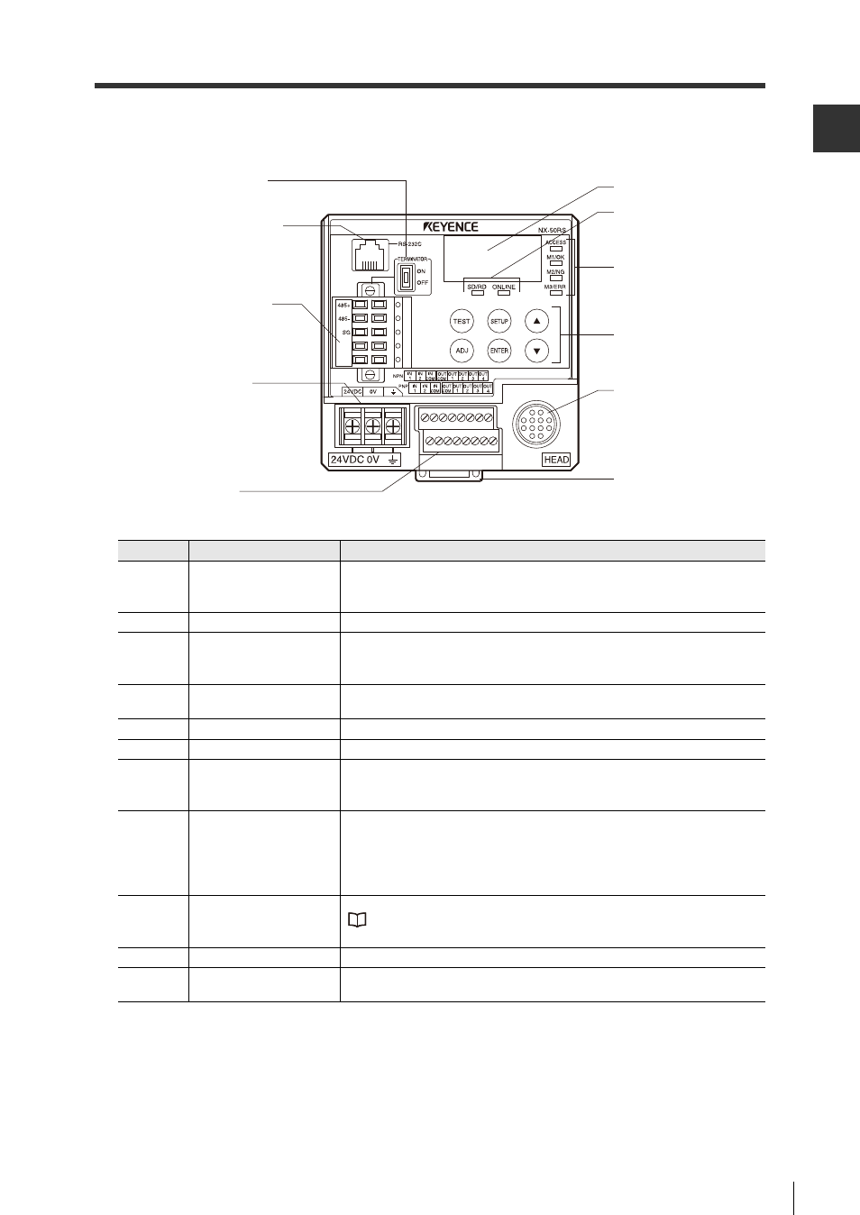
NX-50RS
Front panel
Number
Name
Function
1
Terminator switch
Toggles the terminator.
Turns on when the network controller is at the end of the main line. Turns off
at all other times.
2
RS-232C connector
Used to connect to a computer.
3
RS-485 connector
Used to connect to a field network.
Used when connecting a device such as a network controller to a
multi-drop connection.
4
Power terminal
Used to connect to a 24 V DC power supply. Use a D type ground for
the FG pin.
5
Input/output terminal
Connects input devices such as PLC via NPN/PNP.
6
Display
Displays the status of the network controller.
7
Network communication
status LED
Displays the communication status of the network.
SD/RD:
Displays whether data is being sent or received.
Online:
Displays whether the device is online.
8
Head communication
state LED
Displays the communication status of the head via LED.
Access: Illuminates
when
the head is communicating.
M1/OK:
Illuminates when the head is outputting an OK signal.
M2/NG:
Illuminates when the head is outputting an NG signal.
M3/ERR: Illuminates when the head is outputting an error signal.
9
Control switch
Used to control the network.
"RF-500 Series Setup and Connection Manual" "4-1 Network Controller
Functions"
10
Head connector
Connects to the head or the code reader.
11
DIN rail mounting
bracket
Mounting bracket for DIN rails.
1. Terminator switch
2. RS-232C connector
3. RS-485 connector
4. Power terminal
5. Input/output
terminal
6. Display
7. Network
communication
state LED
8. Head
communication
state LED
10. Head connector
11. DIN rail
mounting bracket
9. Control switch