KEYENCE N-410 User Manual
Page 40
2-18
Inst
allatio
2
2-4
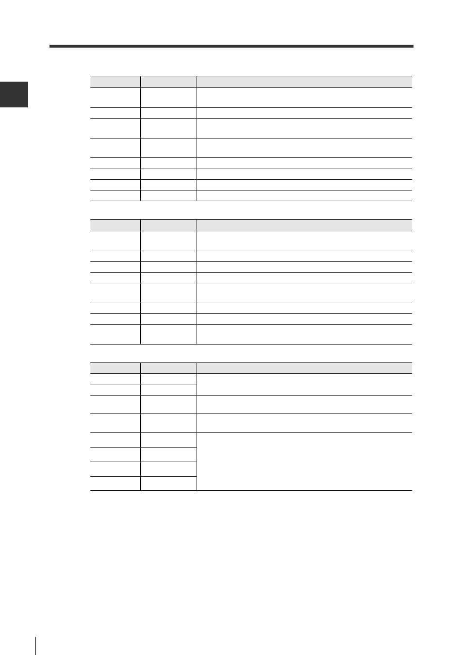
NX-50RS Connections and Wiring
For BL-700/600/180 Series devices
For SR-500 Series devices
For BL-1300 Series/SR-600 Series/RF Series devices
Pin name
Signal name
Explanation
IN1
Trigger input
This is the signal input pin. This is used for trigger input to a BL
Series device.
IN2
-
Not used
INCOM
Trigger input
common
This is the trigger input common.
OUTCOM
Control output
common
This is the output control common.
OUT1
OK output
This pin outputs the signal that the read was successful.
OUT2
NG output
This pin outputs the signal that there was an error in reading.
OUT3
-
Not used
OUT4
-
Not used
Pin name Signal name
Explanation
IN1
Trigger input
This is the signal input pin. This is used for trigger input to a SR
Series device.
IN2
Preset input
This is used for preset input to a SR Series device.
INCOM
Input common
This is the input signal common.
OUTCOM
Output common This is the output signal common.
OUT1
OK output
This pin outputs the signal that the read and the preset were
successful.
OUT2
NG output
This pin outputs the signal that there was an error in preset.
OUT3
ERROR output This pin outputs the signal that there was an error in reading.
OUT4
BUSY output
This pin outputs the signal that the device is in the waiting state or
the preset registration is complete.
Pin name
Signal name
Explanation
IN1
Control input 1
This is the signal input pin.
This is used for an input signal assigned to the head.
IN2
Control input 2
INCOM
Control input
common
This is the input control common.
OUTCOM
Control output
common
This is the output control common.
OUT1
Control output 1
This is the signal input pin.
This is used for an input signal assigned to the head.
OUT2
Control output 2
OUT3
Control output 3
OUT4
Control output 4