Wiring the out 1 through out 4 terminals – KEYENCE N-410 User Manual
Page 35
2-13
2-3
Connecting and Wiring to the N-R4 Series
Inst
allatio
2
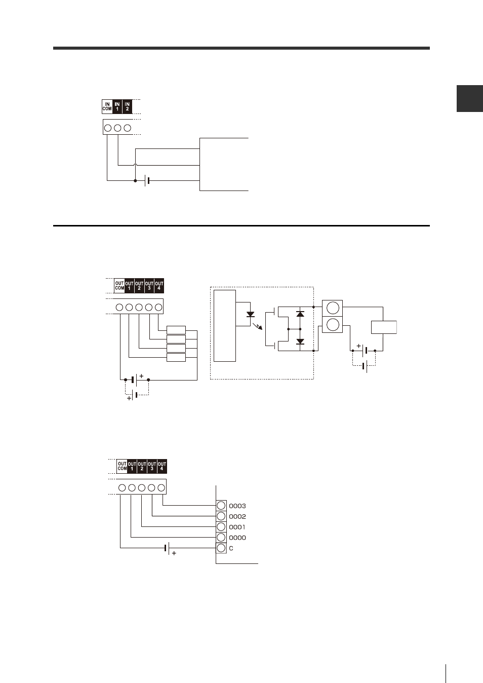
Connection to a photoelectric sensor manufactured by KEYENCE
For this connection, the IN1 terminal is used as the trigger input terminal.
Wiring the OUT 1 through OUT 4 terminals
The OUT terminals can be used to verify OK/NG readings, and other status outputs from the BL-1300
Series.
The output form is photo MOS relay.
Connection to a PLC (programmable logic controller) manufactured by
KEYENCE
Photoelectric sensor
Brown (Red)
Black (White)
Blue (Black)
Load
Load
Load
Load
OUT1 to OUT4
OUTCOM
Load
Circuit diagram
In
ter
nal cir
cuit
PLC
See also other documents in the category KEYENCE Sensors:
- LR-TB2000 Series (12 pages)
- LR-TB5000 Series (12 pages)
- LR-ZB250AN/AP (4 pages)
- LR-ZB250AN/P (3 pages)
- LR-ZBxN/P Series (3 pages)
- LR-ZBxxB (3 pages)
- OP-85135 (1 page)
- PZ-G Series (2 pages)
- PZ-V/M (2 pages)
- PS-N10 Series (12 pages)
- PX-10 (10 pages)
- CZ-V21A(P) (10 pages)
- CZ-K1(P) (8 pages)
- CZ-V1 (8 pages)
- FS-N10 Series (6 pages)
- FS-N10 Series (116 pages)
- FS-N15CN (1 page)
- FU-93(Z) (2 pages)
- FU-V Series (2 pages)
- FS-V30 (6 pages)
- FU-A40 (1 page)
- NU/FS-N Series (16 pages)
- FS-V33(P) (8 pages)
- FS-V21 (4 pages)
- FS-V22 (4 pages)
- FS-V11(P) (4 pages)
- FS-V1(P) (4 pages)
- LV-N10 Series (12 pages)
- LV-N10 Series (112 pages)
- LV-S62 (1 page)
- OP-84350 (1 page)
- LV-SA (10 pages)
- LV-SB (12 pages)
- OP-87305 (1 page)
- LV Series (10 pages)
- LV-B102 (1 page)
- EV-108M(U) (1 page)
- EZ Series (1 page)
- EM Series (1 page)
- ES-M1(P) (3 pages)
- EX-V Series (120 pages)
- EX-500(W) Series (16 pages)
- GV Series (10 pages)
- IA Series (8 pages)
- LB-1000(W) (24 pages)