Rs-232c connections, Rs-232c connections -7, Connecting to a computer – KEYENCE N-410 User Manual
Page 29
2-7
2-2
N-410 Connections and Wiring
Inst
allatio
2
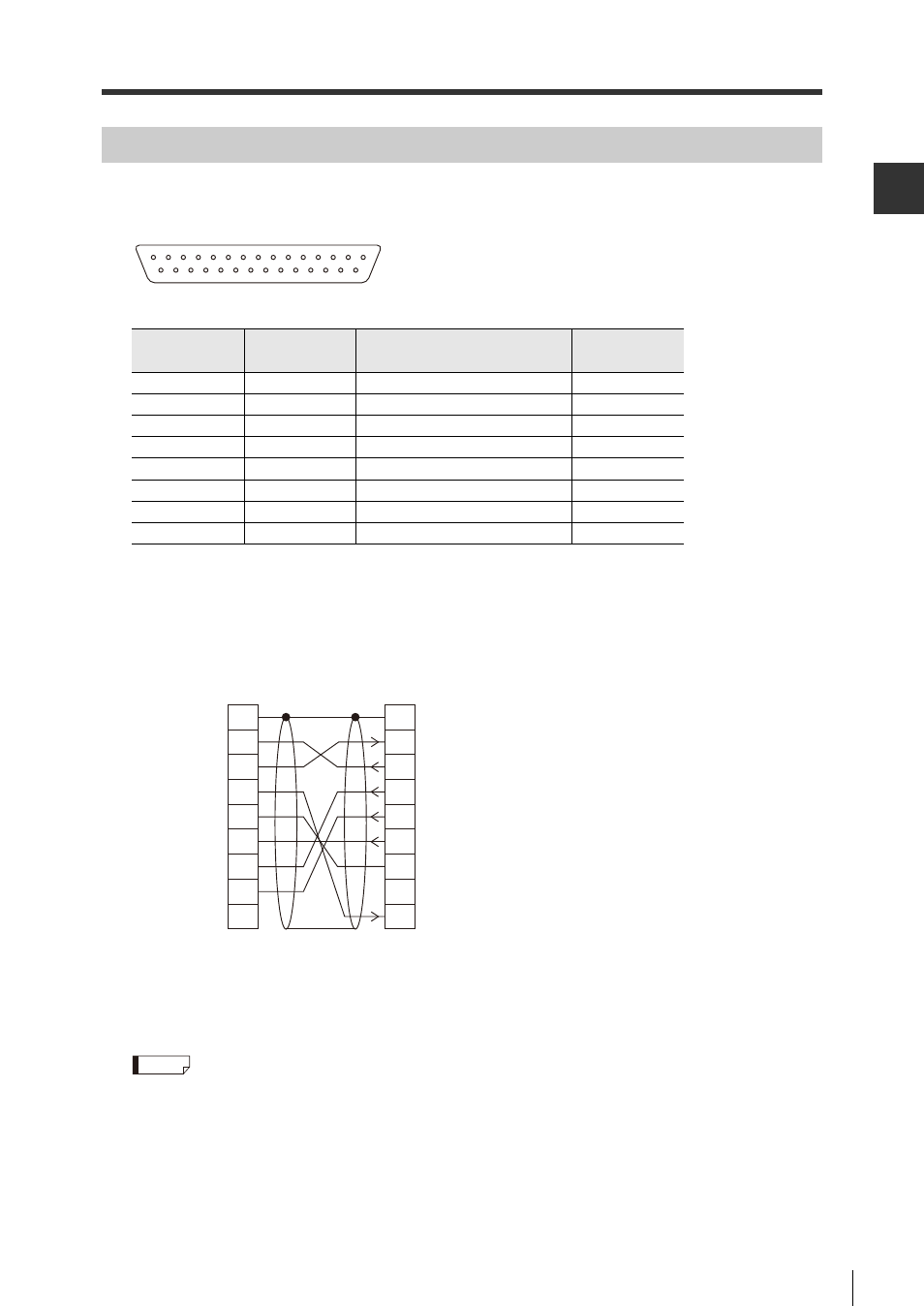
RS-232C Connections
Connecting to a computer
Standard straight cables (D-sub 25 pin or D-sub 25 pin - 9 pin) can be used.
Pin number
Symbol
Function
Signal
direction
1
FG
Frame ground
-
2
SD (TXD)
Receive data
Input
3
RD (RXD)
Send data
Output
4
RS (RTS)
Send capability
Input
5
CS (CTS)
Request send
Output
6
DR (DSR)
Connects internally with pin #20
Output
7
SG
Signal ground
-
20
ER (DTR)
Connects internally with pin #6
Input
13
25
14
1
D-sub 25 pin (female)
DCE specification
(modem definition)
M2.6 screws
Connecting to a DOS/V computer
FG
SD
RD
RS
CS
DR
SG
N-410
-
Connector case
2
RD
3
SD
4
ER
5
SG
6
DR
7
RS
8
CS
DOS/V
CD
1
1
2
3
4
5
6
7
8
ER
20
D-sub 9 pin (female)
#4-40 screws
D-sub 25 pin (male)
M2.6 screws
* A KEYENCE OP-29860 option cable
(1.5m) can be used.
Reference
See also other documents in the category KEYENCE Sensors:
- LR-TB2000 Series (12 pages)
- LR-TB5000 Series (12 pages)
- LR-ZB250AN/AP (4 pages)
- LR-ZB250AN/P (3 pages)
- LR-ZBxN/P Series (3 pages)
- LR-ZBxxB (3 pages)
- OP-85135 (1 page)
- PZ-G Series (2 pages)
- PZ-V/M (2 pages)
- PS-N10 Series (12 pages)
- PX-10 (10 pages)
- CZ-V21A(P) (10 pages)
- CZ-K1(P) (8 pages)
- CZ-V1 (8 pages)
- FS-N10 Series (6 pages)
- FS-N10 Series (116 pages)
- FS-N15CN (1 page)
- FU-93(Z) (2 pages)
- FU-V Series (2 pages)
- FS-V30 (6 pages)
- FU-A40 (1 page)
- NU/FS-N Series (16 pages)
- FS-V33(P) (8 pages)
- FS-V21 (4 pages)
- FS-V22 (4 pages)
- FS-V11(P) (4 pages)
- FS-V1(P) (4 pages)
- LV-N10 Series (12 pages)
- LV-N10 Series (112 pages)
- LV-S62 (1 page)
- OP-84350 (1 page)
- LV-SA (10 pages)
- LV-SB (12 pages)
- OP-87305 (1 page)
- LV Series (10 pages)
- LV-B102 (1 page)
- EV-108M(U) (1 page)
- EZ Series (1 page)
- EM Series (1 page)
- ES-M1(P) (3 pages)
- EX-V Series (120 pages)
- EX-500(W) Series (16 pages)
- GV Series (10 pages)
- IA Series (8 pages)
- LB-1000(W) (24 pages)