I/o terminal layout and wiring, I/o terminal layout and wiring -12, Caution – KEYENCE N-410 User Manual
Page 34: I/o terminal layout and wiring i/o terminal layout, Wiring the in1 and in2 terminals, Applicable crimp terminal
2-12
Inst
allatio
2
2-3
Connecting and Wiring to the N-R4 Series
I/O Terminal Layout and Wiring
I/O terminal layout
These terminals are used to connect I/O devices such as a PLC.
•
For connection, use stranded copper wire with a gauge of AWG16 to 26.
•
Limit the tightening torque for the terminal block screws to 0.19 N•m (1.7
Lbf•in) or less.
Standard The power supply terminal block and the I/O terminal block are insulated from each other.
The INCOM and OUTCOM terminals are insulated from each other.
Applicable crimp terminal
Use a bar terminal with the following dimensions for the connection.
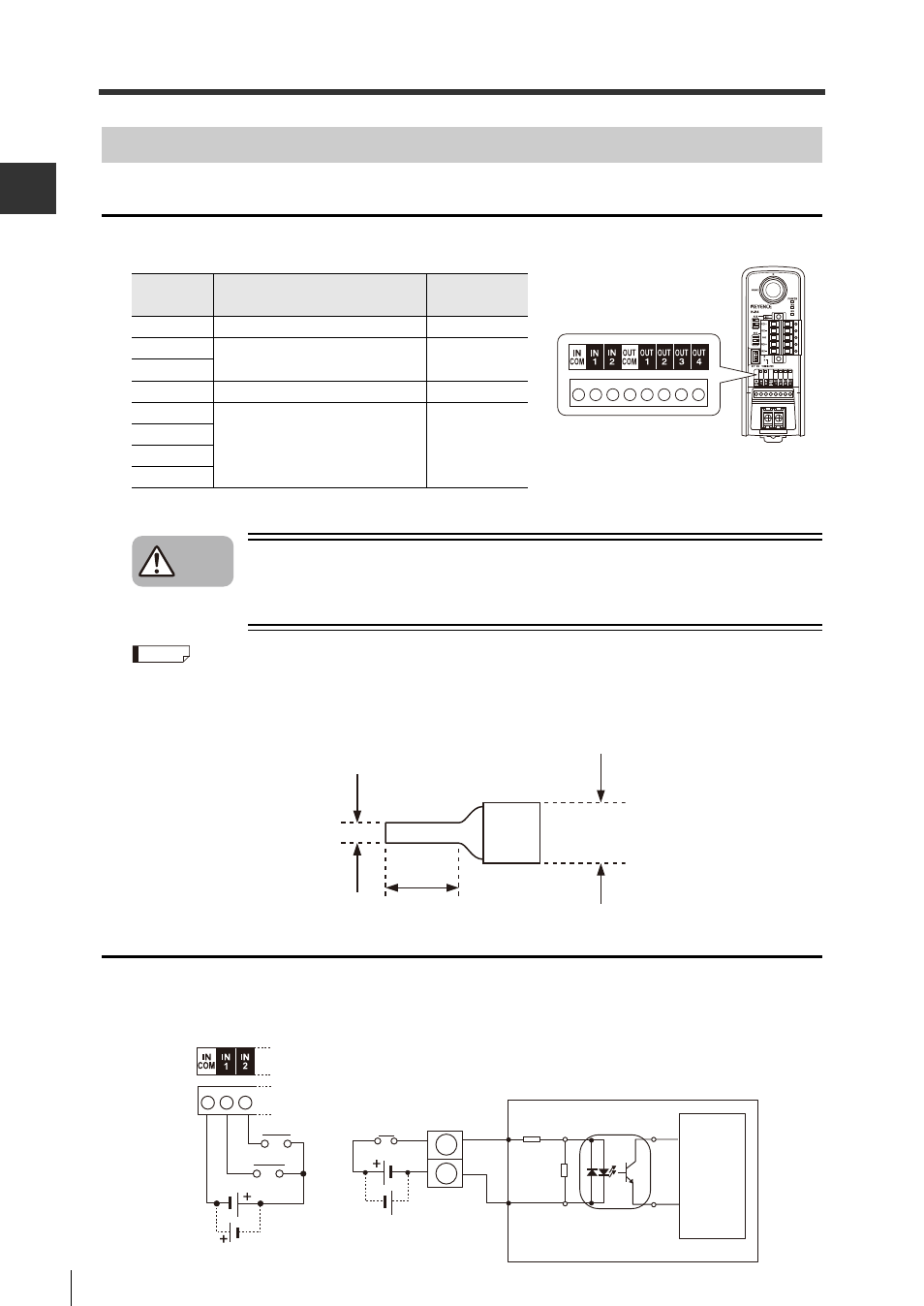
Wiring the IN1 and IN2 terminals
The IN1 and IN2 terminals are used to input trigger signals, to preset registration data, or to send
laser emission stop signals.
The inputs are energized when 15 to 26.4 V DC is connected between the corresponding input terminals.
Symbol
Description
Signal
direction
INCOM
Common for IN terminal
–
IN1
Used as an input terminal for
the code reader.
Input
IN2
OUTCOM Common for OUT terminal
–
OUT1
Used as an output terminal from
the code reader.
Output
OUT2
OUT3
OUT4
* Although the figure shows the model
"N-R2", the I/O terminals are located in
the same position on all models.
Caution
Reference
1.5 mm max.
5 mm max.
3.5 mm max.
Circuit diagram
IN1, IN2
INCOM
Internal
circuit