N-48 – KEYENCE N-410 User Manual
Page 19
1-7
1-3
Part Names
N-410 Overview
1
N-48
Number
Name
Function
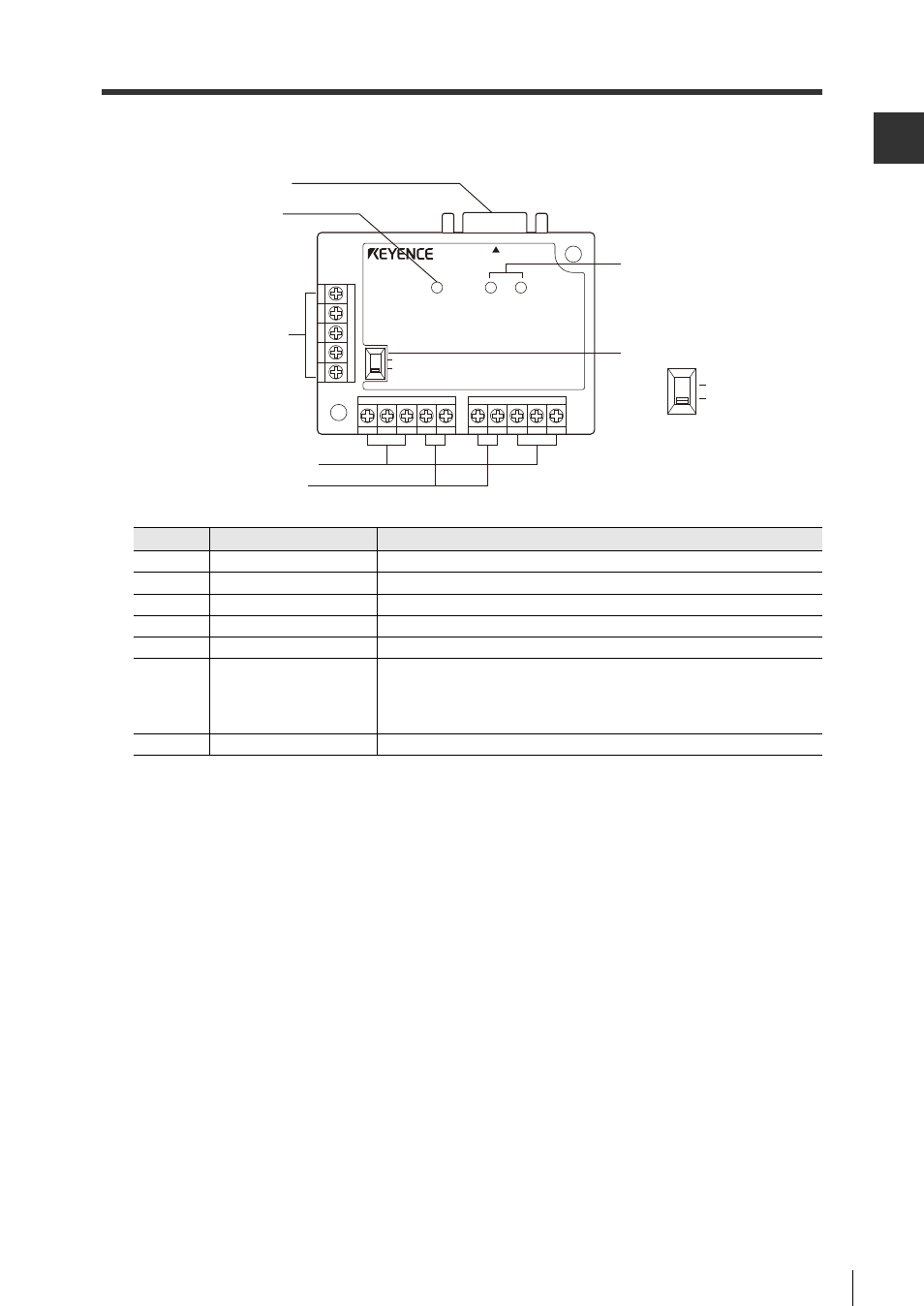
1
Reader port
Connects to BL/SR/RF Series devices.
2
Power LED
Illuminates when power is on.
3
Input/output terminal
There are terminals for input and OK/NG output.
4
RS-485 terminal
Used for multi-drop connections.
5
Power terminal
Connects a 24 V DC power source.
6
Communication state
display LEDs
Monitors the state of communications at the reader port.
SD: Illuminates when a BL/SR/RF Series device sends data.
RD: Illuminates when a BL/SR/RF Series device receives a
command.
7
Terminator switch
Toggles the terminator.
READER
POWER
1. Reader port
2. Power LED
3. Input/output
terminal
4. RS-485 terminal
5. Power terminal
TERMINATOR
ON
OFF
SD
RD
N-48
7. Terminator switch
6. Communication
state display LEDs
ON
OFF
See also other documents in the category KEYENCE Sensors:
- LR-TB2000 Series (12 pages)
- LR-TB5000 Series (12 pages)
- LR-ZB250AN/AP (4 pages)
- LR-ZB250AN/P (3 pages)
- LR-ZBxN/P Series (3 pages)
- LR-ZBxxB (3 pages)
- OP-85135 (1 page)
- PZ-G Series (2 pages)
- PZ-V/M (2 pages)
- PS-N10 Series (12 pages)
- PX-10 (10 pages)
- CZ-V21A(P) (10 pages)
- CZ-K1(P) (8 pages)
- CZ-V1 (8 pages)
- FS-N10 Series (6 pages)
- FS-N10 Series (116 pages)
- FS-N15CN (1 page)
- FU-93(Z) (2 pages)
- FU-V Series (2 pages)
- FS-V30 (6 pages)
- FU-A40 (1 page)
- NU/FS-N Series (16 pages)
- FS-V33(P) (8 pages)
- FS-V21 (4 pages)
- FS-V22 (4 pages)
- FS-V11(P) (4 pages)
- FS-V1(P) (4 pages)
- LV-N10 Series (12 pages)
- LV-N10 Series (112 pages)
- LV-S62 (1 page)
- OP-84350 (1 page)
- LV-SA (10 pages)
- LV-SB (12 pages)
- OP-87305 (1 page)
- LV Series (10 pages)
- LV-B102 (1 page)
- EV-108M(U) (1 page)
- EZ Series (1 page)
- EM Series (1 page)
- ES-M1(P) (3 pages)
- EX-V Series (120 pages)
- EX-500(W) Series (16 pages)
- GV Series (10 pages)
- IA Series (8 pages)
- LB-1000(W) (24 pages)