Caution, Electrical wiring, Wiring the trigger input – KEYENCE N-410 User Manual
Page 44
2-22
Inst
allatio
2
2-5
N-48 Connections and Wiring
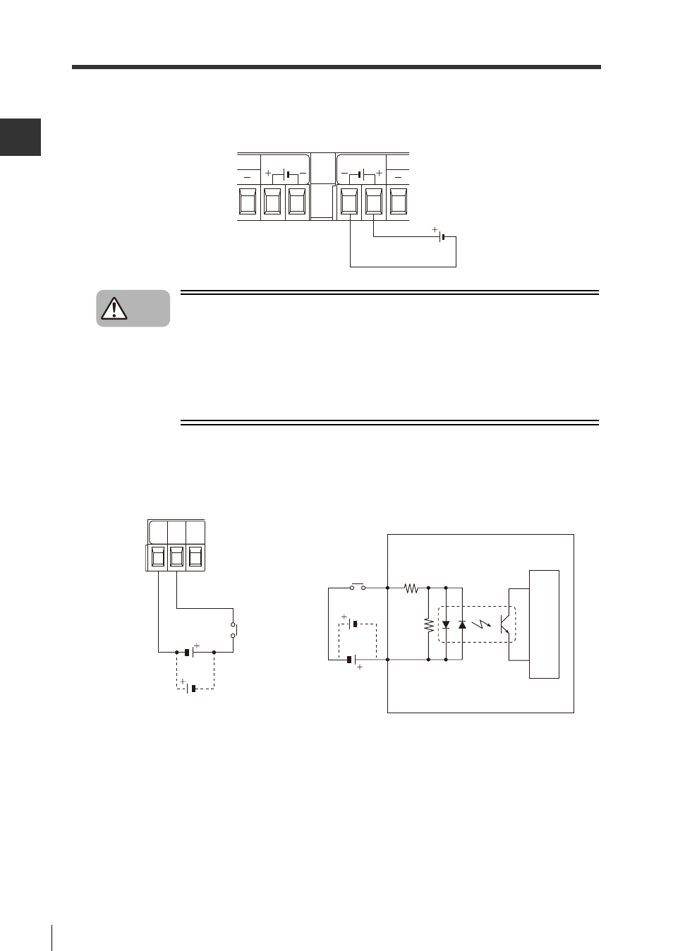
Electrical wiring
Connect a 24 V DC power source to the "IN" side, as shown in the figure.
If 24 V DC power is connected to the "IN" side, the "OUT" side can be used for 24 V DC output.
•
Do not connect to any power voltage other than 24 V DC. Doing so may
damage the device.
•
Connecting an RS-485 terminal to the wrong power supply may cause
damage to the N-48 unit.
•
Do not connect the in and out sides to different types of power sources. A
potential difference between the two power sources could result in
malfunction.
Wiring the trigger input
The trigger input is used to cause a BL/SR/RF Series device to begin reading.
When using the device in multi-head mode, use the trigger input from the N-410 instead of the N-
48.
24V DC OUT
24V DC IN
24V DC
Caution
15 to 26 V DC
TIM COM OK
Circuit diagram
Inter
nal circuit
TIM
COM
- LR-TB2000 Series (12 pages)
- LR-TB5000 Series (12 pages)
- LR-ZB250AN/AP (4 pages)
- LR-ZB250AN/P (3 pages)
- LR-ZBxN/P Series (3 pages)
- LR-ZBxxB (3 pages)
- OP-85135 (1 page)
- PZ-G Series (2 pages)
- PZ-V/M (2 pages)
- PS-N10 Series (12 pages)
- PX-10 (10 pages)
- CZ-V21A(P) (10 pages)
- CZ-K1(P) (8 pages)
- CZ-V1 (8 pages)
- FS-N10 Series (6 pages)
- FS-N10 Series (116 pages)
- FS-N15CN (1 page)
- FU-93(Z) (2 pages)
- FU-V Series (2 pages)
- FS-V30 (6 pages)
- FU-A40 (1 page)
- NU/FS-N Series (16 pages)
- FS-V33(P) (8 pages)
- FS-V21 (4 pages)
- FS-V22 (4 pages)
- FS-V11(P) (4 pages)
- FS-V1(P) (4 pages)
- LV-N10 Series (12 pages)
- LV-N10 Series (112 pages)
- LV-S62 (1 page)
- OP-84350 (1 page)
- LV-SA (10 pages)
- LV-SB (12 pages)
- OP-87305 (1 page)
- LV Series (10 pages)
- LV-B102 (1 page)
- EV-108M(U) (1 page)
- EZ Series (1 page)
- EM Series (1 page)
- ES-M1(P) (3 pages)
- EX-V Series (120 pages)
- EX-500(W) Series (16 pages)
- GV Series (10 pages)
- IA Series (8 pages)
- LB-1000(W) (24 pages)