KEYENCE N-410 User Manual
Page 121
7-5
7-2
Device Assignments
PLC
7
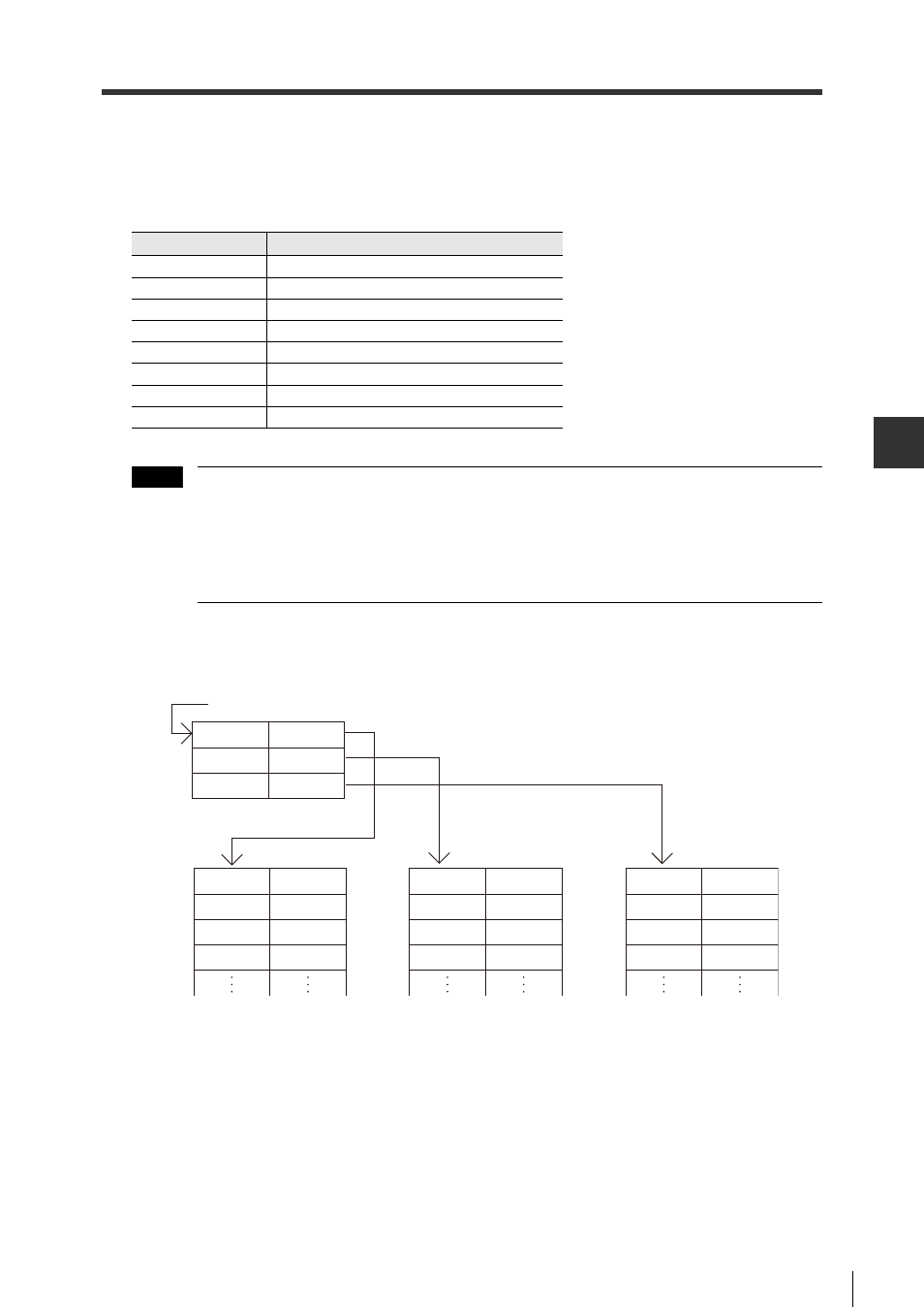
(Write location area for each ID number)
Data write areas can be assigned as follows by assigning "+02 to +32" to the "write header
address" (A). If there are 10 BL Series or SR Series devices connected, the following read data
will be divided into 10 parts in and saved in 10 separate write areas. (This is the case if each ID
number has a distinct data write header address).
Up to 255 digits worth of data can be saved in this data area.
BL Series devices can only store up to 96 digits worth of data (when using BL-210RK), but
SR Series devices can store 2D code data far more than 255 digits (up to 7089 digits: QR
code).
However, note that when using a PLC link, data over 255 digits cannot be stored into a
PLC.
Header address = 100, 3 devices connected (ID numbers 1, 2 and 3)
Address
Contents
A+00
Data write flag area
A+01
ID number
A+02
Digits
A+03
1st and 2nd digits of data
A+04
3rd and 4th digits of data
A+05
5th and 6th digits of data
:
:
A+130
255th digit of data
Note
(Example)
Header address 100
DM100
DM101
DM102
200
300
400
(ID1)
(ID2)
(ID3)
DM200
DM201
DM202
DM203
Flag
ID
Digits
1st and 2nd
digits of data
DM300
DM301
DM302
DM303
Flag
ID
Digits
1st and 2nd
digits of data
DM400
DM401
DM402
DM403
Flag
ID
Digits
1st and 2nd
digits of data