2 n-410 connections and wiring, Installing and wiring the input and output jacks, N-410 connections and wiring -5 – KEYENCE N-410 User Manual
Page 27: N-410 connections and wiring, Electrical wiring
Inst
allatio
2
2-5
2-2
N-410 Connections and Wiring
This section explains how to connect the N-410 to other devices.
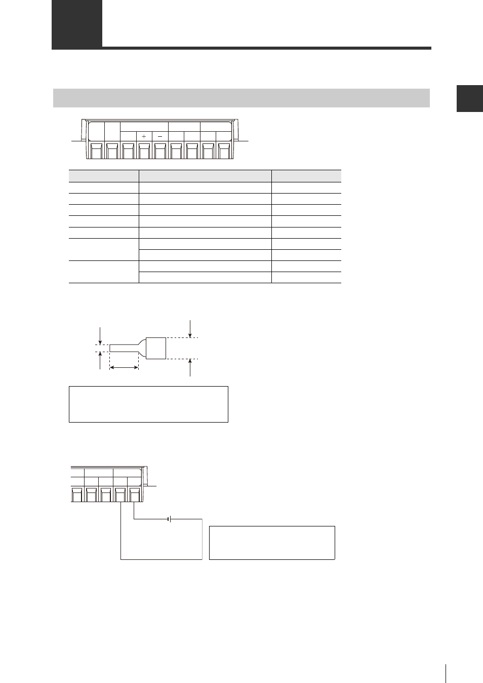
Installing and Wiring the Input and Output Jacks
* These appear in this order from left to right on the terminal.
• A bar terminal (I terminal) like that shown in the figure can be used.
Electrical wiring
Connect the N-410 to a 24 V DC power supply.
Connect the 24 V DC power source to the "IN" side of the power terminal to use the "OUT" side of
the terminal as a 24 V DC power supply (However, be certain that the power supply coming into
the "IN" side is will have enough power to power the device connected to the "OUT side").
Symbol
Explanation
Signal direction
TIM
Trigger input
Input
COM
Trigger input common
Input
RS-485 SG
RS-485 ground signal
-
RS-485 +
RS-485 + side
Input/output
RS-485 -
RS-485 - side
Input/output
DC OUT
24 V DC power source output + side
Output
24 V DC power source output - side
Output
DC IN
24 V DC power source input + side
Input
24 V DC power source input - side
Input
RS-485
TIM COM
SG
24V
0V
24V
0V
DC OUT
DC IN
5 mm max.
6 mm min.
2.0 mm
max.
Recommended manufacturer:
Maker: JST Manufacturing Company, Ltd.
Model: VTUB-1.25
–
DC OUT
DC IN
24V DC
+
24V
0V
24V
0V
Use an NEC class 2 output
power source for UL
certification.