5 n-48 connections and wiring, Connecting to a bl/sr/rf series device, N-48 connections and wiring -20 – KEYENCE N-410 User Manual
Page 42: Connecting to a bl/sr/rf series device -20, N-48 connections and wiring, Pin layout
2-20
Inst
allatio
2
2-5
N-48 Connections and Wiring
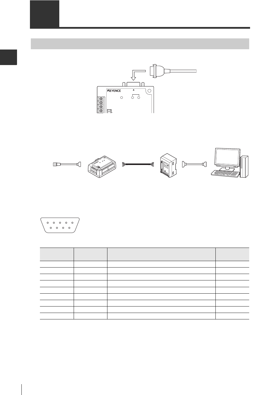
Connecting to a BL/SR/RF Series Device
Connect a BL-700/600/180 Series or 210RK device to the reader board of the N-48.
When connecting a BL-1300 Series/SR Series/RF Series device to the N-48, use a option D-sub
converter cable (RF-CM2D).
* The baud rate of a code reader connected to the N-48 should be 38400 bps or less.
Pin Layout
N-48
BL series
READER
POWER
TERMINATOR
ON
SD
RD
N-48
N-410
Computer
RS-232C cable
(OP-29860)
RS-485
twist pair cable
D-sub converter cable
(RF-CM2D)
(BL-1300, SR:OP-80616)
Pin number
Symbol
Function
Signal
direction
1
TIM
Trigger input
Output
2
RD (RXD)
Send data
Output
3
SD (TXD)
Receive data
Input
4
OK
OK
Input
5
GND (SG)
Ground (Common ground for all signals)
-
6
NG
NG
Input
7
RS (RTS)
Send capability
Input
8
CS (CTS)
Request send
Output
9
+5V
5 V power source output (600mA)
Output
6 7 8 9
1 2 3 4 5
D-sub9 pin (male)
DCE specification
(modem definition)
#4-40 screws