Installation – Lenze 8200 Frequency inverters User Manual
Page 97
Installation
8200SHB0199
4-40
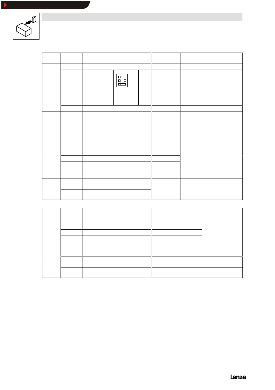
Terminal
Use
(Factory setting is printed in bold)
Level
Data
Analog
inputs
7
GND 1
Analog
inputs
8
Setpoint input,
reference:
Terminal 7
(0 to 10 V)
6
4
2
5
3
1
5 - 6
5 - 6
3 - 4
1 - 2
0 to 20 mA
4 to 20 mA
0 to 5 V
0 to 10 V
Resolution: 820X: 9 bit,
821X/822X/824X: 10 bit
Linearity fault:
0.5 %
Temperature fault: 0.3 % (0 ... + 40
C)
Input resistance
Voltage signal: > 100 k
Jumper
Input resistance
Voltage signal: > 100 k
Current signal: 250
9
Supply for setpoint potentiometer
5.2 V / 6 mA
Analog
output
62
Analog output, reference: Terminal 7
(Field frequency)
0 ... 6 V / 2 mA
0 ... 10 V / 2 mA
1)
Resolution: 820X: 8 bit
821X/822X/824X: 10 bit
Digital
inputs
20
Voltage supply for digital inputs
820X: 12 V / 20 mA
821X/822X/824X: 15 V / 20 mA
28
Controller enable
HIGH
HIGH:
12 V ... 30 V
LOW:
0 V ... 3 V
E4
CW/
CCW rotation (CW/CCW)
CW: LOW
CCW: HIGH
HIGH:
12 V ... 30 V
LOW:
0 V ... 3 V
E3
DC-injection brake
HIGH
E2
JOG frequencies
20 Hz, 30 Hz, 40 Hz
Binary code
E1
JOG frequencies
20 Hz, 30 Hz, 40 Hz
Binary code
39
GND 2 (reference for external voltages)
Monitoring T1
Motor-temperature monitoring
(PTC thermistor/thermal contact)
If not used: Set parameter C119 = -0-!
T2
Motor-temperature monitoring
(PTC thermistor/thermal contact)
Terminal
Use
(Factory setting is printed in bold)
Relay position (switched)
Data
Relay
output K1
K 11
Relay output normally-closed contact
(TRIP)
Opened
24 V AC / 3.0 A or
60 V DC / 0.5 A
output K1
K 22
Relay mid-position contact
60 V DC / 0.5 A
K 24
Relay output normally-open contact
(TRIP)
Closed
Relay
output K2
K 21
Relay output normally-closed contact
(Ready for operation)
Opened
250 V AC / 3.0 A or
60 V DC / 0.5 A
output K2
K 22
Relay mid-position contact
250 V AC / 3.0 A or
60 V DC / 0.5 A
K 24
Relay output normally-open contact
(Ready for operation)
Closed
250 V AC / 3.0 A or
60 V DC / 0.5 A
1)
With 821X/822X/824X HVAC (V020)
Show/Hide Bookmarks