Configuration – Lenze 8200 Frequency inverters User Manual
Page 231
Configuration
8200SHB0199
7-94
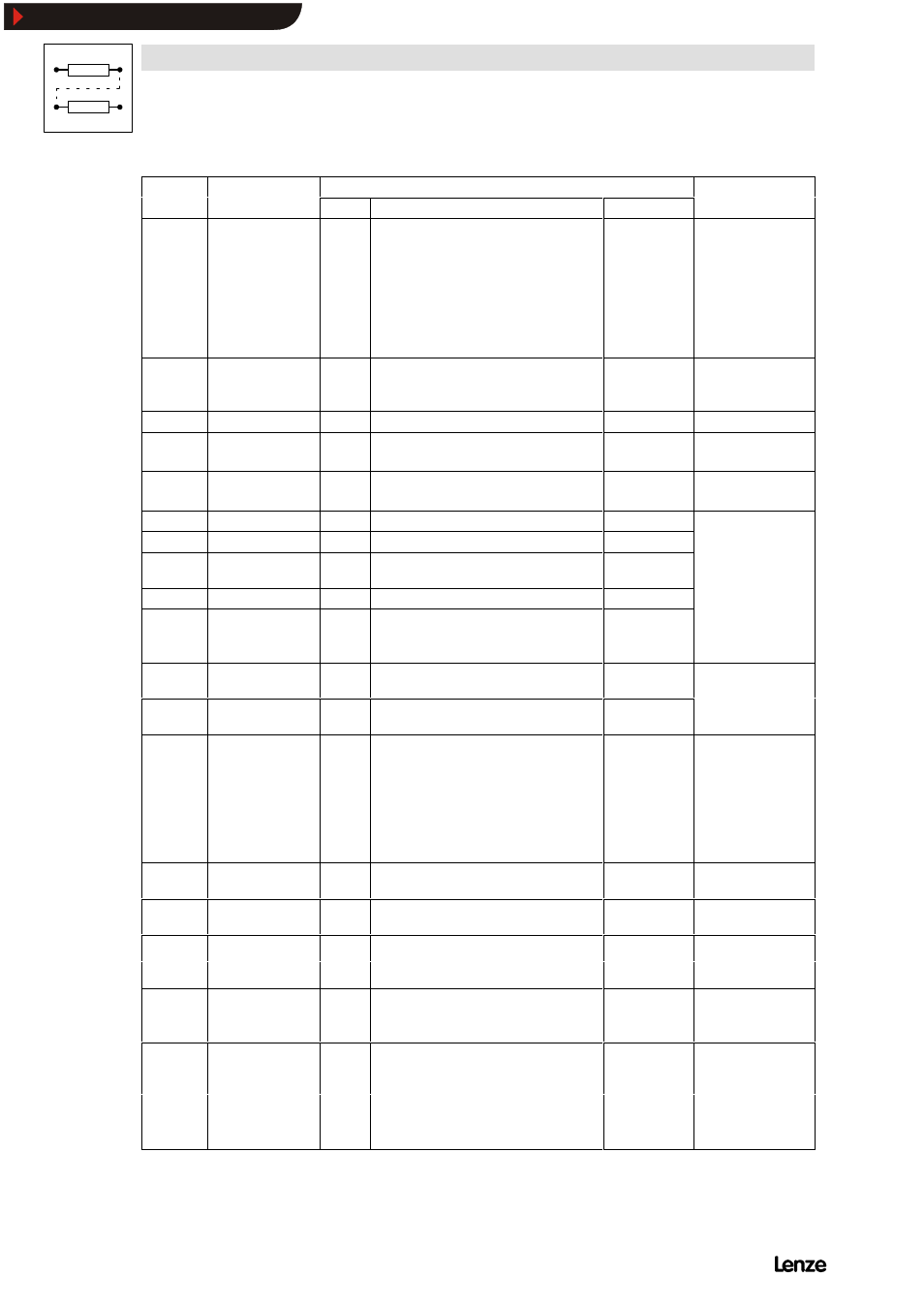
Code
IMPORTANT
Possible settings
Name
Code
IMPORTANT
Info
Choice
Lenze
Name
C182* Integration time
ramp function
generator S-shape
0.00
0.00
{0.01 s}
50.00 Page 7-32
-
C182 = 0.00
- Linear ramp
function generator
-
C182 > 0.00
- Ramp function
generator S shape
with
T
i
time = C182
C196*
¤ Input condition
autom. DC injection
brake
-0-
-0-
DC brake active at C050 < C019
-1-
DC brake active at C050 < C019
and Setpoint < C019
Page 7-56
C200 Software EKZ
C238
¤ Frequency
precontrol
-1-
-0-
No precontrol
-1-
With setpoint precontrol
Page 7-34,
7-39
C239
¤ Frequency setting
range
-0-
-0-
Bipolar
-1-
Unipolar
Page 7-39
C304 Password1
C305 Password2
C307 Contents of the
address
Should only be
changed by the
C308 Address
changed by the
Lenze Service!
C377*
¤ Gain voltage
detection
822X/824X
Lenze Service!
C395 LWORD process
input data
Only for bus operation
C396 LWORD process
output data
Only for bus operation
C425
¤* Adjustment of digital
frequency
-2-
Dig.-
Reso-
Scann-
Max.-
freq.
lution
ing
freq.
-0-
100 Hz 1/200
1 s
300 Hz
-1-
1 kHz
1/200
100 ms
3 kHz
-2-
10 kHz 1/200
10 ms
10 kHz
-3-
10 kHz 1/1000
50 ms
10 kHz
-4-
10 kHz 1/10000 500 ms 10 kHz
Page 7-60
When using the
analog input module
9279 for the
frequency input E1:
-
Set C425 to 2, 3
or 4
C426* Gain adjustment
frequency input E1
100
-200.0
{0.1 %}
200.0 Page 7-60
C427 Offset adjustment
frequency input E1
0.0
-12.5
{0.1 %}
12.5 Page 7-60
C500* Display factor
Application datum
2000
1
{1}
25000 Page 7-63
Application datum
numerator
C501* Display factor for
process variable
10
1
{1}
25000 Page 7-63
process variable
denominator
C597*
¤ Activation of motor
phase failure
detection
Page 7-73
822X/824X
-0-
-0-
Inactive
-1-
TRIP
-2-
Warning
Show/Hide Bookmarks