Application examples – Lenze 8200 Frequency inverters User Manual
Page 286
Application examples
8200SHB0199
15-7
Application FIG 15-3:
The material speed v
2
is to be synchronised to the line speed v
1
by means of a
dancer-position control. The dancer-position setpoint is internally set.
Functions used
-
Internal PID controller as position controller.
-
Selection of the line speed v
1
via terminal 8.
-
Act. dancer position from the dancer potentiometer to the analog plug-in
module 8279IB.
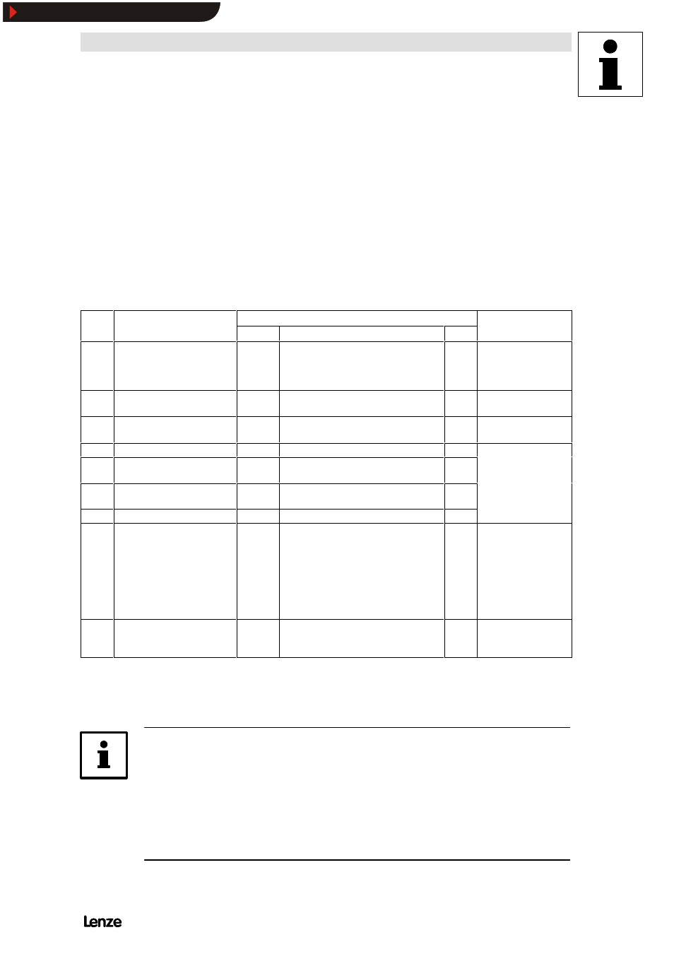
Code settings:
Code
Name
Possible settings
IMPORTANT
Code
Name
Lenze
Choice
Info
IMPORTANT
C005 Configuration
-0-
-6-
Controlled operation; setpoint via
terminal 8 with digital frequency
feedback via terminal E1
Jumper setting for
terminal 8 must be
adapted to 5 V (see
chapter 4.2.8.2).
C007 Terminal configuration
-0-
-49-
Actual dancer position
via terminal E1
C037 JOG value 1
20.00
Fixed in-take speed v
1
for material
guidance, individually adjustable
C070 Gain PID controller
1.00
C071 Integral action time PID
controller
100
Adaptation to process
C072 Differential component PID
controller
0.0
Adaptation to process
C074 Influence PID controller
0.0
10.0 %
C105 Deceleration time QSP
5.00
Enter approx. 1 s
Emergency-stop
function:
-
The drive geometry
must be adjusted so
that it is possible to
brake the controller to
standstill within a very
short time.
C239 Frequency setting range
-0-
-1-
Unipolar
Direction of rotation
cannot be changed via
the process controller.
All other parameters are based on the factory setting.
Set the rated motor data under C088 (rated motor current) and C091 (motor cos
Ö) depending on the motor
connected.
Note!
-
For more detailed information on the process controller, see chapter
7.5.10.
-
Calibration of the setpoints and actual values to the application datum under
C500 and C501.
(See chapter 7.6.3)
Show/Hide Bookmarks