Configuration – Lenze 8200 Frequency inverters User Manual
Page 188
Configuration
8200SHB0199
7-51
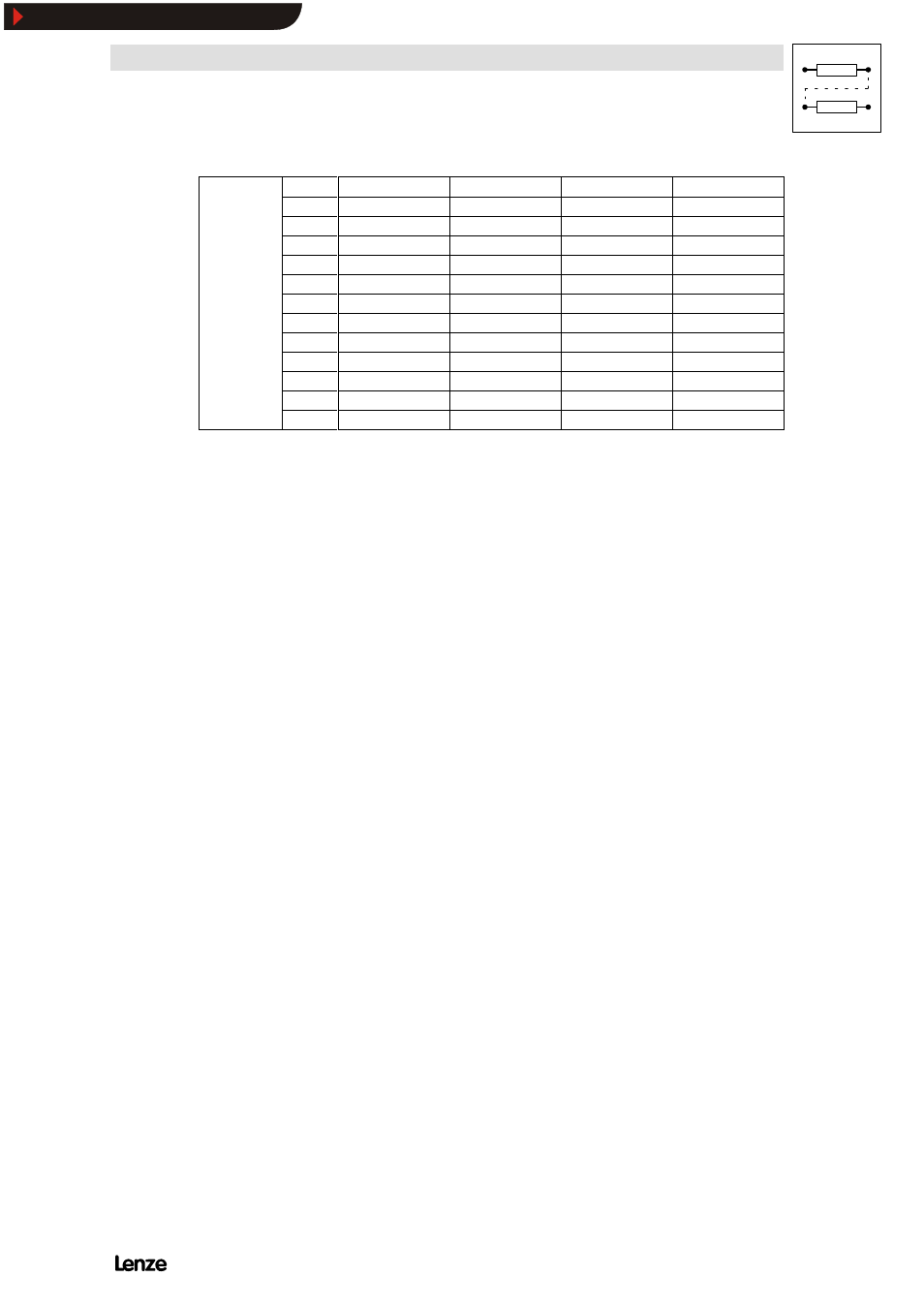
C007
E1
E2
E3
E4
only
series “HVAC”
-40-
D/F
TRIP set
QSP
JOG1
only
series “HVAC”
-41-
D/F
TRIP set
DC injection brake
JOG1
-42-
D/F
TRIP set
DC injection brake
QSP
-43-
D/F
TRIP set
QSP
CW/CCW
-44-
D/F
PAR
DOWN
UP
-45-
D/F
PAR
QSP
CW/CCW
-46-
JOG1
QSP
PAR
H/Re
-47-
JOG1
H/Re
CCW/QSP
CW/QSP
-48-
D/F
I-OFF
DC injection brake
INFL_0
-49-
D/F
QSP
JOG1
INFL_0
-50-
D/F
I-OFF
JOG1
INFL_0
-51-
D/F
I-OFF
PAR
DCB
Function
Depending on your application you can select a function group under C007. A binary signal code at
the digital inputs E1 ... E4 activates the functions.
Important
Response time of the inputs E1 ... E4:
820X
16 ... 24 ms
821X/822X/824X
2.5 ... 4 ms
Special features
820X
The digital inputs E1 ... E4 are without function when using the operating mode ”Control via
LECOM” (C001 = -3-).
821X/822X/824X
With the operating mode ”Control via LECOM” (C001= -3-), the functions ”TRIP set” and ”QSP”
remain effective.
Series “HVAC”
With the operating mode ”Control via LECOM” (C001= -3-), the functions ”TRIP set” and ”QSP”
remain effective. They can be switched-off with the priority mask (C115).
-
The levels for the input terminals can be inverter under C114.
-
Use the following terminal configuration, if terminal E1 is used for the setpoint or the act. value:
(see chapter 7.5.14.9)
- C007 = -28- ... -45, -48- ... -51-
Show/Hide Bookmarks