1 signal-flow chart for types 820x, 1 control structure, Signal-flow chart for types 820x – Lenze 8200 Frequency inverters User Manual
Page 293: Control structure, Signal flow charts, Show/hide bookmarks
Signal flow charts
8200SHB0199
16-2
16.1
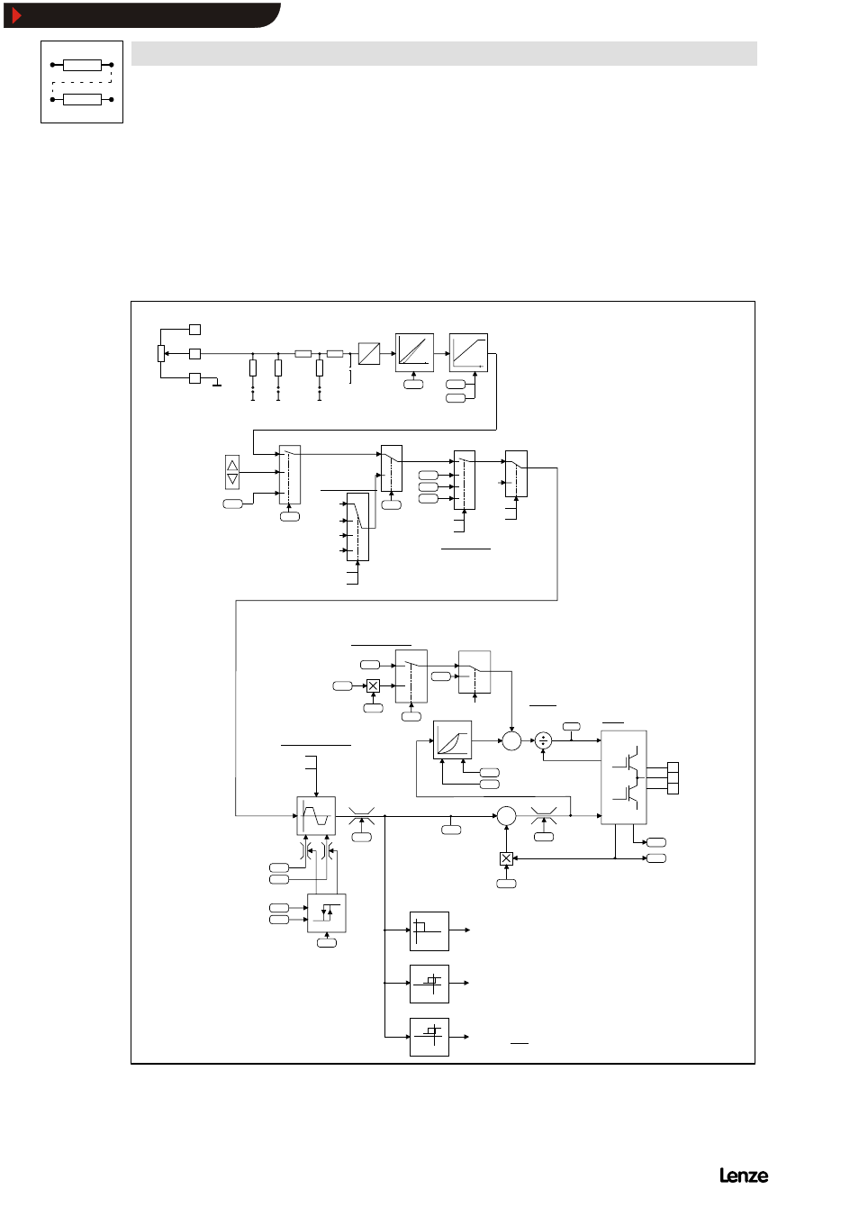
Signal-flow chart for types 820X
16.1.1
Control structure
Ctrl.
enable
DC
brake
Reset
C011
fdmax
C050
fd
+
+
C021
+
+
C016
2.3
C016
C056
Vmin
Vmin
Autoboost
Calculation of voltage
0.1
C014
Control
mode
C036
Inverter
Slip compensation
C054
Motor current IMot [A]
(act. value)
C056 Load display [%]
0.2
1.3
fd = fdset
Qmin reached
(Hysteresis = )
fdmax
128
0.1 Hz
fdset
0.1 Hz
C012
C013
C022
C023
C056
Ramp function generator
VDC br.
fd = 0Hz
C015
C014
V/f ref. point
V/f characteristic
fd = 0Hz
U
V
W
9
8
7
GND
internal
REF
+ 5.2V
A
D
50k
100k
250R
100k
50k
12
34
56
Jumper
Filter
10n
0 4
20
0
1
C034
Offset
C011
fdmax
C010
fdmin
8201BB
Operating
unit
Setpoint
serial
interface
3
1
0,2
C001
Motor potentiometer
Constant
UP
DOWN
C007
Setpoint selection
00
01
10
11
0 - 9
14 - 20
JOG 1
JOG 2
QSP
DC brake
V
0 - 20mA
4 - 20mA
0 - 5V
0 - 10V
C046
10 - 13
21 - 22
0Hz
Bedienungsart
C038
C037
C039
0Hz
UP
DOWN
fdset
fdset
C052
Motor voltage
Vz - comp.
fd act
C011
FIG 16-1
Signal flow 8200: Control structure
Show/Hide Bookmarks