Festo Контроллеры двигателя SFC-LAC User Manual
Page 69
3. Installation
3−17
Festo GDCP−SFC−LACI−CO−EN en 0812NH
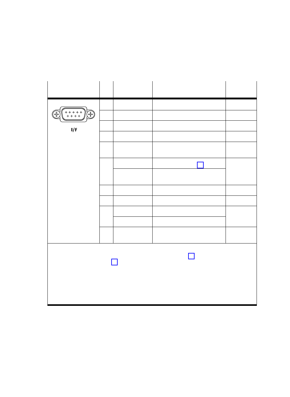
Connection
Pin
Designation
Function
Fieldbus
plug
1)
1
5
1
n.c.
Not connected
ć
2
CAN_L
CAN bus low
A/L
6
9
3
5)
CAN GND
CAN bus reference potential
GND
4
n.c.
Not connected
ć
5
Screened
Capacitive connection to housing
Clamping
strap
6
2)
5)
GND logic
3)
Logic power GND (see Tab. 3/3)
ć
5)
GND bus
4)
Bus interface power supply
reference potential
7
CAN_H
CAN bus high
B/H
8
n.c.
Not connected
ć
9
2)
n.c.
3)
Not connected
V+
24 V bus
4)
Power supply to the bus interface
ć
Screening/housĆ
ing
Connection to (FE) functional
earth
Clamping
strap
1)
Pin assignment on fieldbus plug type FBS−SUB−9−BU−2x5POL−B from Festo
2) Depending on parameterisation CAN Voltage Supply" (see section 5.2.1) or [CAN Volt.Supply]
on control panel (see section 4.5.6, [CO parameters] ).
3) Internal supply of the fieldbus node (default): CAN bus (pins 2, 3, 7) referred to logic voltage of
the SFC−LACI.
·
Do not connect pins 6 and 9.
4) External supply of the fieldbus node: CAN bus (pins 2, 3, 7) referred to external power supply
(permits electrically isolated bus connection).
·
Pin 6 and pin 9 must be supplied with 24 V.
5) Pin 3 and pin 6 are connected internally with each other in the SFC−LACI−CO.
Tab. 3/8: I/F" terminal (control terminal) on the SFC−LACI−...−CO