Festo Контроллеры двигателя SFC-LAC User Manual
Page 193
5. Commissioning
5−91
Festo GDCP−SFC−LACI−CO−EN en 0812NH
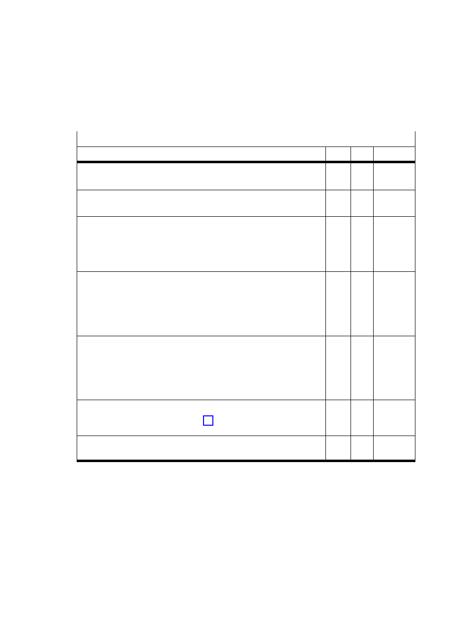
Overview of parameters when using a brake/clamping unit
Parameter / Description
PNU
FCT
CI
Out1: Use
Value = 1: Out1 is the defined brake output
1240
x
2421/01h
Out2: Use
Value = 1: Out2 is the defined brake output
1250
x
2422/01h
Switch−on delay
Time in [ms] between setting the enable (ENABLE = 1) or a START signal
(if the automatic brake is activated) and the start of a positioning motion.
The brake can open completely in this period of time.
Values: 0...500 ms.
1310
x
6510/17h
Switch−off delay
Time in [ms] between the removal of the enable (ENABLE = 0) or the
expiry of the activation time of the automatic brake and the switching off
of the SFC−LACI’s output stage. In this period of time, the SFC−LACI conĆ
tinues to control the position, and the brake can close completely.
Values: 0...500 ms.
1311
x
6510/18h
Activation time of the automatic brake
Time in [s] between the completion of a positioning motion (Motion
complete") and the resetting of the brake output (providing in this period
of time there is no new START signal). The switch−off delay follows after
the activation time.
Value = 0 deactivates the automatic brake.
1312
x
6510/19h
PWM value
Duty cycle during a period of time. See Fig. 5/10.
Values: 1...100%. Value = 0 deactivates the pulse−width modulation.
1259
x
2422/09h
Display of brake status
Bit 0 = 1 / 0: The configured brake output is set / not set.
304
x
60FE/01h
Tab. 5/22: Parameters when using a brake/clamping unit