Description of the control bytes ccon, cpos, cdir – Festo Контроллеры двигателя SFC-LAC User Manual
Page 144
5. Commissioning
5−42
Festo GDCP−SFC−LACI−CO−EN en 0812NH
5.5.5
Description of the control bytes CCON, CPOS, CDIR
CCON
With control byte 1 (CCON) all the states which must be availĆ
able in all operating modes are controlled. The cooperation of
the control bits can be found under the description of the
drive functions in section 5.6.
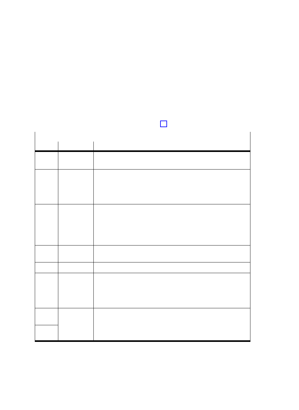
Control byte 1 (CCON)
Bit
EN
Description
B0
ENABLE
Enable Drive
= 1: Drive (controller) enable
= 0: Drive (controller) blocked
B1
STOP
Stop
= 1: Enable drive.
Any error will be deleted.
= 0: STOP active: The axis stops with the fast stop ramp (Quick Stop) or
with the normal stop ramp (compare PNUĂ1020/605Dh).
The positioning task counts as finished.
B2
BRAKE
Brake
If the SFC−LACI is
not in the ready" state (status word does not equal
operation_enable"):
= 0: Close brake / clamping unit
= 1: Open brake / clamping unit.
In the ready" status, the controller takes over the control of the brake
output. Controlling the output via the PLC is then not possible.
B3
RESET
Reset Fault
With a rising edge a fault is acknowledged and the fault number is deĆ
leted.
B4
ć
reserved, must be at 0
B5
LOCK
Lock
HMI access
Controls access to the parameterisation interface:
= 1: MMI and FCT may only observe the drive, the device control (HMI
control) cannot be taken over by MMI and FCT.
= 0: MMI or FCT may take over the device control (in order to modify
parameters or to control inputs)
B6
OPM1
Select
Operating
Mode
= 00:
Record selection
= 01:
Direct mode
10
Reserved
B7
OPM2
Mode
= 10:
Reserved
= 11:
Reserved