Pf3000, Ag leader technology – Ag Leader PF3000 Harvest & Application Operators Manual User Manual
Page 247
PF3000
System Wiring
Ag Leader Technology
April 2002
7-7
System Wiring
Refer to the last page to see a table of the pin-outs of the combine cables for
the PF3000.
Checking Flow
Sensor
Connections
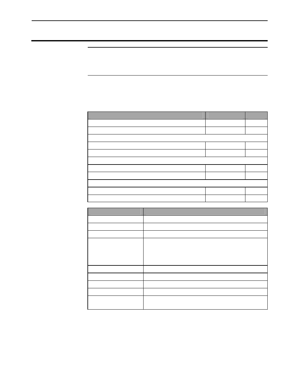
To check the flow sensor for electrical connection, use an ohmmeter and
check for the following resistance’s (readings can be 1-3 ohms off and still
be good readings):
Check at:
Pins
Ohms
Cab Cable (rectangular 25 pin conn.)
9 + 21
350
Cab Cable (rectangular 25 pin conn.)
8 + 22
375
Distribution Cable (large round 24 pin conn.)
8 + 19
350
Distribution Cable (large round 24 pin conn.)
7 + 20
375
Flow Sensor Ext. Cable (round 9 pin conn.)
2 + 3
350
Flow Sensor Ext. Cable (round 9 pin conn.)
1 + 4
375
Flow Sensor Cable (round 9 pin conn.)
2 + 3
350
Flow Sensor Cable (round 9 pin conn.)
1 + 4
375
Pin-Out of Port 1
Pin
Signal
1
Regulated 5 volts (limit current draw to 50 ma)
2
RS-232 Transmit (from monitor)
3
RS-232 Receive (into monitor)
4
12 Volt Power (switched, reverse polarity
protected, limit current draw to 1
amp) The PF3000 must be ON for
current to flow.
5
RS-232 Ground
6
Ground
7
Second RS-232 Transmit (not in use)
8
Second RS-232 Receive (not in use)
9
Auxiliary A/D Input (keep input voltage between
ground and 5 volts)