HP Integrated Lights-Out 2 User Manual
Page 126
16.100.226.32. If you set the interconnect bay EBIPA range to 16.200.139.51 to 16.209.139.58,
the interconnect module management port in interconnect bay #1 is assigned 16.200.139.51
and the interconnect module management port in interconnect bay #7 is assigned 16.200.139.57.
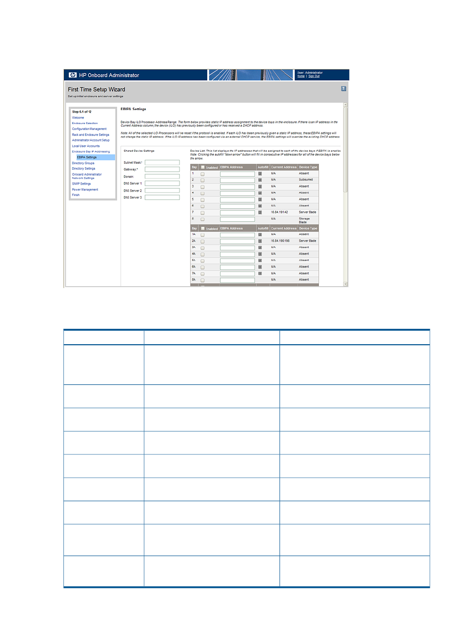
To enable EBIPA settings for the server bays in this enclosure, select Enable Enclosure Bay IP
Addressing for Server Bay iLO 2 Processors, then enter the following information.
Description
Possible value
Field
Beginning IP address for the device or
interconnect bays. Click the arrow next to the
###.###.###.### where ### ranges from
0 to 255
Beginning Address
Beginning Address field, and click Update List
to update the Device List or Interconnect List.
Subnet mask for the device or interconnect bays
###.###.###.### where ### ranges from
0 to 255
Subnet Mask
Gateway address for the device or interconnect
bays
###.###.###.### where ### ranges from
0 to 255
Gateway
The domain name for the device or interconnect
bays
A character string, including all
alphanumeric characters and the dash (-)
Domain
The IP address for the primary DNS server
###.###.###.### where ### ranges from
0 to 255
DNS Server 1
The IP address for the secondary DNS server
###.###.###.### where ### ranges from
0 to 255
DNS Server 2
The IP address for the tertiary DNS server
###.###.###.### where ### ranges from
0 to 255
DNS Server 3
The IP address of the primary server used to
synchronize time and date using the NTP
protocol
###.###.###.### where ### ranges from
0 to 255
NTP Server 1
The IP address of the secondary server used to
synchronize time and date using the NTP
protocol
###.###.###.### where ### ranges from
0 to 255
NTP Server 2
126
Using iLO 2