FEC FUSIONE-HS-2 User Manual
Page 88
Chapter 4: System Setup and Wiring
Page 4-50
Configuration
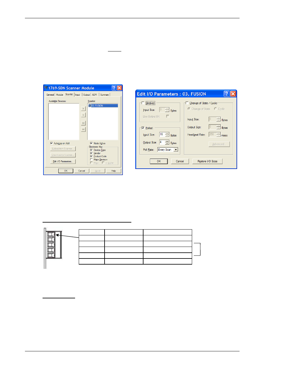
FEC DeviceNet I/O is pre-configured according to the I/O Signal Map (See below). Configu-
ration of the DeviceNet Master MUST match the size configuration of the FEC DeviceNet
slave or the network will not connect/operate properly. In the DeviceNet Master set-up using
RSNetworx, set the Input/Output length using the “Polled” option. When setting the Device-
Net Master I/O configuration, Input size refers to FEC output size (ie. Accept, Reject, Busy,
etc.) and Output size refers to FEC inputs (ie. Start, Stop, Reset, etc.). See the below
screen shots of this configuration using RSNetworx.
DeviceNet Interface Connections
Pin No.
Signal
Wire Color
1
V-
Black
2
CAN_L
Blue
3
Drain/Shield
4
CAN_H
White
5
V+
Red
Termination
Termination of the DeviceNet network requires a terminating resistor at each end of the net-
work. These resistors should have a value of 121 ohms.
See “Termination”