FEC FUSIONE-HS-2 User Manual
Page 41
FEC FUSION Operations Manual
Chapter 4: System Setup and Wiring (Rev. 2.1)
Page 4-3
4.2 Component Dimensions
The specifications for all of the FUSION standard system equipment are outlined in this
Chapter to aid in determining space, mounting & wiring requirements.
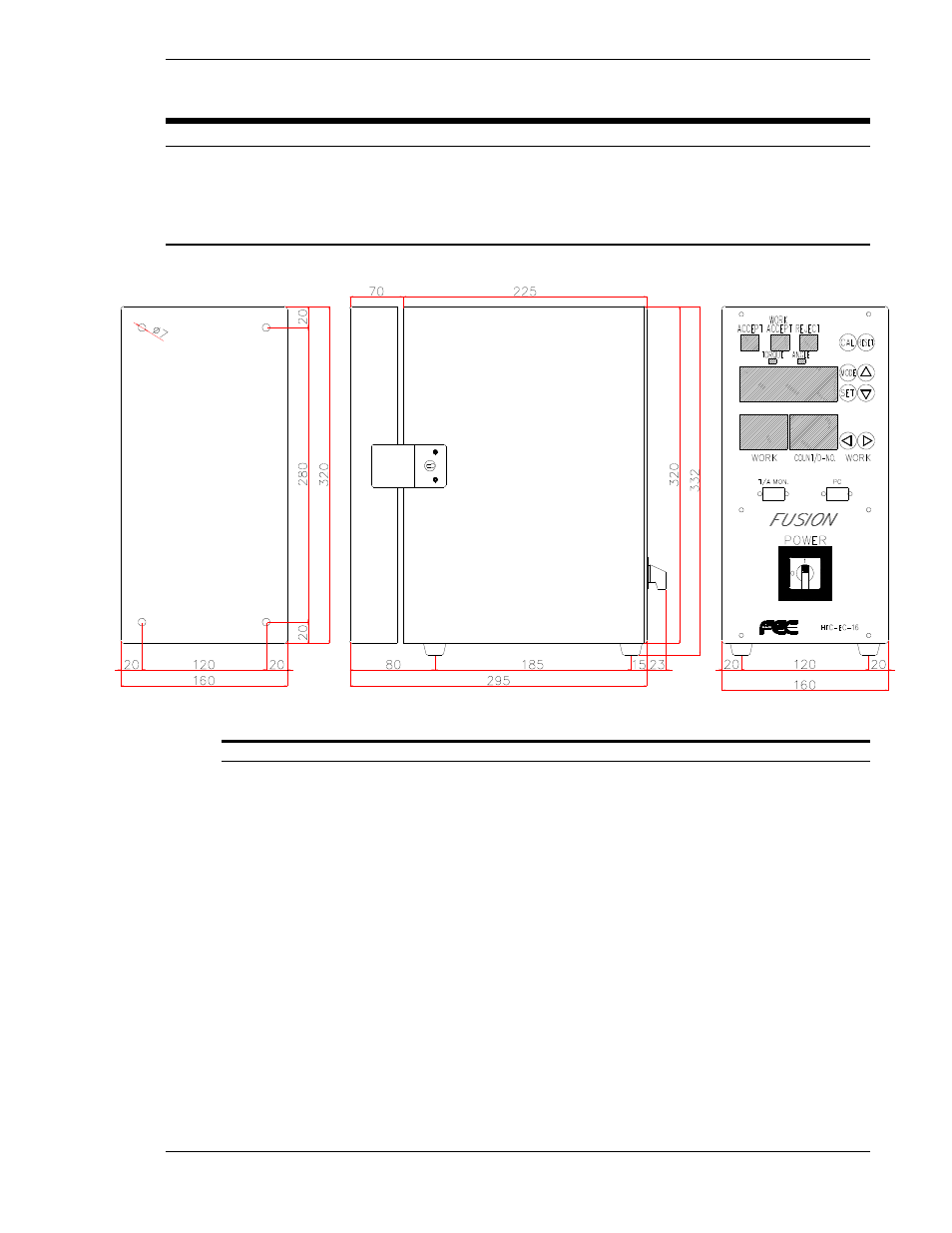
4.2.1 CONTROLLER Unit Dimensions
FIG. 4-2-1 Controller Unit Dimensions
Controller weight is 8.6 Kg (18.9lbs.)
The Unit(s) must be mounted with a minimum clearance of 25mm on the left side and 126mm
on the right side to allow for proper heat dissipation. If mounting multiple controllers side by
side you must leave a minimum clearance of 260mm between the units for clearance when
opening the back cover. Programming Cable connections on the front of the Unit require
100mm of clearance. Cable connections on the rear of the Units require 150mm of clearance
below the unit for exiting the Rear cover other than straight down. Controller Units must be
located at a minimum 300mm from any high transient voltage power source. High transient
sources such as relays, AC contactors, AC motor drives, etc. may cause malfunction of the
FUSION Controller unit. All motor cables and I/O cables must be run separate from all high
transient voltage sources. When locating inside an enclosure, avoid mounting at or near the
top where internal enclosure heat is most extreme.
The controller of the FUSION System is designed with 4 mounting holes for easy mounting to
a back panel using standard 6mm screws.