FEC FUSIONE-HS-2 User Manual
Page 72
Chapter 4: System Setup and Wiring
Page 4-34
4.13 SYNC Connector
The Sync connector is provided for a means to synchronize more than one spindle during the
fastening process. Synchronized fastening allows spindles to synchronize at a preset torque
before attempting to reach the next target or final torque. For synchronized fastening opera-
tion using individual Fusion controllers, the SYNC terminals must be wired between all af-
fected spindles.
The SYNC signals are Bi-directional signals for synchronized fastening (5V, TTL signal).
1. At the start of the cycle until reaching the synchronization point (1st torque), the SYNC
signal is ON (LOW condition) to stop other Fusion Units from continuing to the second
step (wired OR).
2. When the 1st torque is reached, the signal works as an input signal. If it reads LOW -
meaning that other Fusion units have not reached 1st torque yet - the Fusion unit stays in
the standby state waiting for all connected spindles to reach first torque.
When the SYNC signal is HIGH (all Fusion units have completed the first step), all units si-
multaneously start the second step.
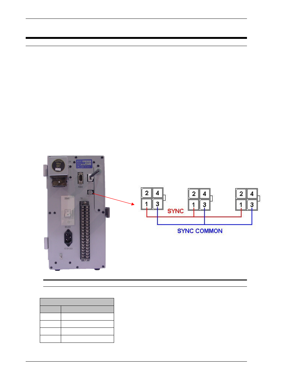
Fig. 4.13 Sync Connector
CN6 (Sync Connector)
PIN
DESCRIPTION
1
Sync Signal (5V TTL)
2
Not Used
3
Sync Common (0v)
4
Frame Ground (FG)
Spindle SYNC signals are connected in series from
one spindle to the next.