FEC FUSIONE-HS-2 User Manual
Page 67
FEC FUSION Operations Manual
4.11 Tool Cable Connection
•
Tools are connected to the
ducer preamp, motor and
fication number and should be connected to the corresponding
•
Cables should be supported to reduce fatigue points
allow the cable to move, but yet hold it in place. Cable tie
point leading to premature cable failure.
WARNING:
Do not make motor connections with the power on. Turn off all controller power
before attempting to connect or disconnect any motor cables
Recommended cable length:
Maximum cable length:
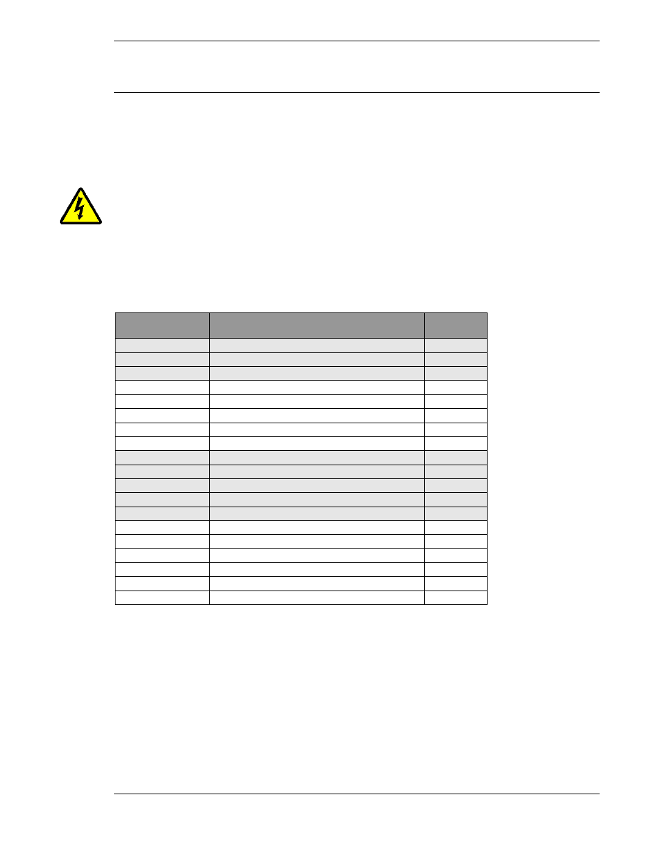
Fusion Cable List
FEC Part #
FEB-1309-M5
Main Cable Straight Female Plug
FEB-1309-M10
Main Cable Straight Female
FEB-1309-M15
Main Cable Straight Female Plug
FEB-1311-M5
Main Cable 90 Degree Female Plug
FEB-1311-M10
Main Cable 90 Degree Female Plug
FEB-1311-M15
Main Cable 90 Degree Female Plug
FEB-1310-M1
Extension Cable Straight Female Plug
FEB-1310-M2
Extension Cable Straight Female Plug
FEB-1310-M3
Extension Cable Straight Female Plug
FEB-1310-M5
Extension Cable Straight Female Plug
FEB-1310-M10
Extension
FEB-1312-M1
Extension Cable 90
FEB-1312-M2
Extension Cable 90
FEB-1312-M3
Extension Cable 90
FEB-1312-M5
Extension Cable 90
FEB-1312-M10
Extension Cable 90
Wave Washer (Part # WAV
sired. The washer must be split and inserted by threading the washer
ers.
FEC FUSION Operations Manual
Chapter 4: System Setup and Wiring (Rev. 2.1)
Page 4-29
Connection
Tools are connected to the controller using one cable. One cable connects to the
and resolver. Each cable should be labeled with a specific
number and should be connected to the corresponding controller and
supported to reduce fatigue points. Cable tie points should be loose enough to
allow the cable to move, but yet hold it in place. Cable tie points that are too tight cause a stress
point leading to premature cable failure.
Do not make motor connections with the power on. Turn off all controller power
before attempting to connect or disconnect any motor cables
or tool damage may occur.
able length: 75’ or less.
100’ (must be free from Electrical Noise)
Cable Description
Length
Main Cable Straight Female Plug
5 meter
Main Cable Straight Female Plug
10 meter
Main Cable Straight Female Plug
15 meter
Main Cable 90 Degree Female Plug
5 meter
Main Cable 90 Degree Female Plug
10 meter
Main Cable 90 Degree Female Plug
15 meter
Extension Cable Straight Female Plug
1 meter
Extension Cable Straight Female Plug
2 meter
Extension Cable Straight Female Plug
3 meter
Extension Cable Straight Female Plug
5 meter
Extension Cable Straight Female Plug
10 meter
Extension Cable 90 Degree Female Plug
1 meter
Extension Cable 90 Degree Female Plug
2 meter
Extension Cable 90 Degree Female Plug
3 meter
Extension Cable 90 Degree Female Plug
5 meter
Extension Cable 90 Degree Female Plug
10 meter
Wave Washer (Part # WAV-25036) can be used to tighten the tool side twist lock connector is d
sired. The washer must be split and inserted by threading the washer underneath the twist lock rol
Chapter 4: System Setup and Wiring (Rev. 2.1)
cable. One cable connects to the torque trans-
specific spindle or identi-
and tool.
should be loose enough to
too tight cause a stress
Do not make motor connections with the power on. Turn off all controller power
or tool damage may occur.
25036) can be used to tighten the tool side twist lock connector is de-
underneath the twist lock roll-