FEC FUSIONE-HS-2 User Manual
Page 49
FEC FUSION Operations Manual
4.7
Wiring PLC I/O
All interface devices must accommodate active true low logic for correct operation with
FUSION CONTROLLER
provided for isolated connection to an external controller.
available. Outputs are rated at 12~24 VDC, 200mA. When activated, open collector sink
outputs (normally high) pull the input device signal low (0 VD
and activated when pulled low (0 VDC).
Once wired, the TB1
ing the captive screws located at the top and bottom of the
over to a new controller without disconnecting the terminal wires.
CAUTION
:
The PLC I/O wiring must be routed a minimum of 300 mm away from any transient high vo
tage sources. Cable length must not exceed 50 feet.
DO NOT connect a positive DC
* Output signals shown on terminals A11
SELECT inputs are used, these outputs WILL CHANGE DEFINITION
Select output table
FEC FUSION Operations Manual
Chapter 4: System Setup and Wiring (Rev. 2.1)
Page 4-11
All interface devices must accommodate active true low logic for correct operation with
CONTROLLER Unit DC inputs and outputs (I/O). Four output relay
provided for isolated connection to an external controller. Optional Fieldbus interface
Outputs are rated at 12~24 VDC, 200mA. When activated, open collector sink
outputs (normally high) pull the input device signal low (0 VDC). Inputs are (normally high)
and activated when pulled low (0 VDC).
TB1 terminal block can be quick disconnected from the Controller by
aptive screws located at the top and bottom of the terminal strip, for quick
over to a new controller without disconnecting the terminal wires.
The PLC I/O wiring must be routed a minimum of 300 mm away from any transient high vo
tage sources. Cable length must not exceed 50 feet.
DO NOT connect a positive DC voltage source to the output common.
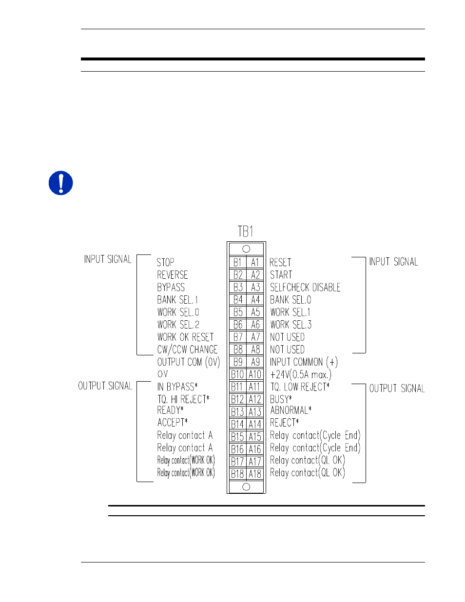
FIG. 4-7-1 Controller Unit PLC Connector
Output signals shown on terminals A11 – B14 are for BANK 1 signals only. If BANK
SELECT inputs are used, these outputs WILL CHANGE DEFINITION according to the Bank
and the selection of BANK SELECT INPUTS.
Chapter 4: System Setup and Wiring (Rev. 2.1)
All interface devices must accommodate active true low logic for correct operation with the
Four output relay contacts are
ieldbus interfaces are
Outputs are rated at 12~24 VDC, 200mA. When activated, open collector sink
C). Inputs are (normally high)
erminal block can be quick disconnected from the Controller by loosen-
terminal strip, for quick change-
The PLC I/O wiring must be routed a minimum of 300 mm away from any transient high vol-
B14 are for BANK 1 signals only. If BANK
according to the Bank