FEC FUSIONE-HS-2 User Manual
Page 170
Chapter 9: Troubleshooting
Page 9-2
9.1 Abnormal Conditions.
When an abnormal condition is detected by the system, the affected spindle stops, and lights
“Abn” in the [DATA] display. For ease of troubleshooting the nature of the abnormal, the sys-
tem provides an abnormal code in the [PARM] display and an abnormal sub-code in the
[COUNT/D-NO] display.
Note: ABNORMALS are not to be confused with fastening REJECTS. Abnormal’s signify a
failure of a system process or self check during the fastening cycle.
•
Abnormal code display
.
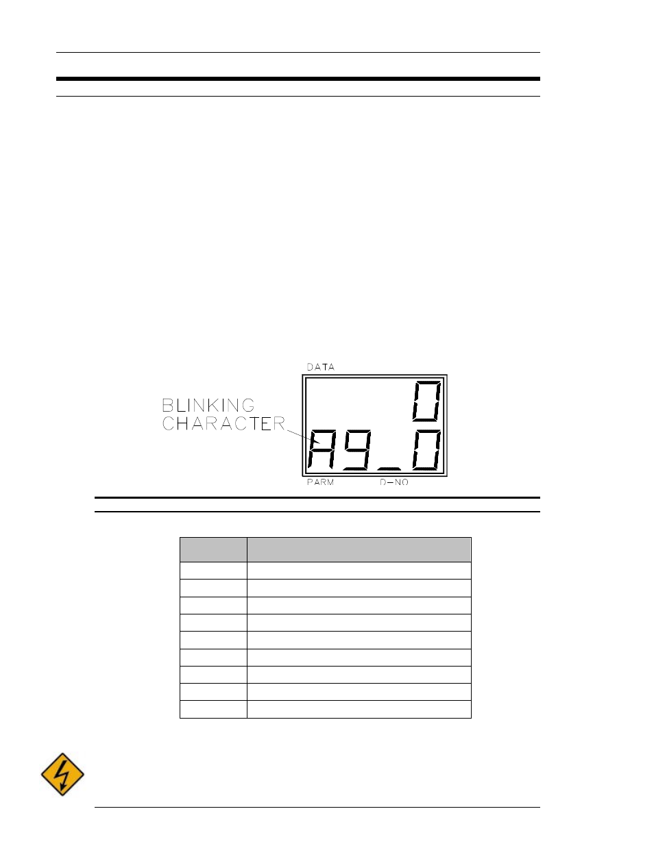
When an Abnormal condition occurs, the display mode will automatically change to the
STATUS mode. (If the display is not in the STATUS mode, depress the MODE button until a
blinking “A” appears in the [WORK] display area) A code number appears at the right side of
the blinking character. This code refers to some specific type of failure detailed in the tables
shown in the following sections.
•
Abnormal Sub-code display
.
The number shown at the most right position in the [COUNT/D-NO] display area is a sub-
code that can be used in conjunction with the Abnormal failure code to further narrow down
the cause of the fault. See the following sections.
Example of Abnormal Code 9 Sub-Code 0
Abnormal Code Table
ABNORMAL
CODE
DESCRIPTION
1
Torque Transducer Error.
2
Over Torque Error.
3
Tool EEPROM error.
4
System Memory Error.
5
Servo Amplifier Reply Error.
6
Servo Type Mismatch Error.
7
NOT USED
8
Servo Amplifier Error.
9
Parameter Error.
Abnormal sub-codes and specific actions for troubleshooting are detailed in the following
section.
WARNING:DO NOT CONNECT OR DISCONNECT CABLES OR OTHER SYSTEM
COMPONENTS WITH POWER APPLIED.