FEC FUSIONE-HS-2 User Manual
Page 55
FEC FUSION Operations Manual
Chapter 4: System Setup and Wiring (Rev. 2.1)
Page 4-17
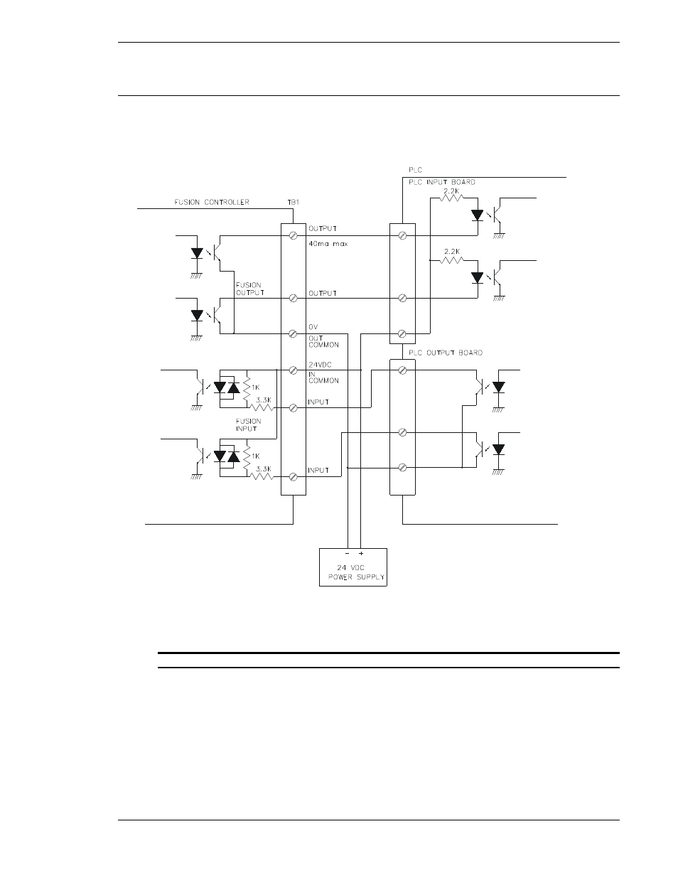
4.7.5 PLC Wiring Sample
This diagram represents standard I/O connections to a PLC. The 24VDC power can be sup-
plied from the FUSION controller (terminals A10,B10) if total consumption is less than 0.5A.
FIG. 4-7-5 PLC Wiring Sample
All inputs and outputs (I/O) are active true low. All interface devices must accommodate ac-
tive true low logic for correct operation. Outputs are rated at +12~24 VDC, 40mA. When ac-
tivated, open collector sink outputs (normally high) pull the input device signal low (0 VDC).
Inputs are sourced (normally high) and activated when pulled low (0 VDC).
See also other documents in the category FEC Accessories for electrical:
- AFC1500 (4 pages)
- AFC1500 (14 pages)
- AFC1500 (20 pages)
- AFC1500 (2 pages)
- AFC1500 (63 pages)
- AFC1500 (83 pages)
- AFC1500 (129 pages)
- AFC1500 (198 pages)
- AFC1200 (6 pages)
- AFC1200 (8 pages)
- AFC1200 (12 pages)
- AFC1200 (5 pages)
- AFC1200 (22 pages)
- AFC1200 (34 pages)
- AFC1200 (16 pages)
- AFC1200 (9 pages)
- AFC1200 (13 pages)
- AFC1200 (4 pages)
- AFC1200 (23 pages)
- AFC1200 (42 pages)
- AFC1200 (10 pages)
- AFC1200 (33 pages)
- AFC1200 (14 pages)
- AFC1200 (24 pages)
- AFC1200 (93 pages)
- AFC1200 (30 pages)
- AFC1200 (90 pages)
- AFC1150 (4 pages)
- AFC1150 (10 pages)
- AFC1150 (18 pages)
- AFC1150 (6 pages)
- AFC1100 (7 pages)
- AFC1100 (9 pages)
- AFC1100 (4 pages)
- AFC1100 (13 pages)
- AFC1100 (21 pages)
- AFC1100 (8 pages)
- AFC1100 (28 pages)
- AFC1100 (18 pages)
- MICRO NR (118 pages)
- DSP1500 (SAN3) (6 pages)
- DSP1500 (SAN3) (10 pages)
- DSP1500 (SAN3) (8 pages)
- DSP1500 (SAN3) (26 pages)