FEC FUSIONE-HS-2 User Manual
Page 129
FUSION Operations Manual
7.2 Run State Modes.
The FUSION system has two operational states that are controlled by
“MODE” and “SET” Buttons, on the front of the Controller, simultaneously,
pass input. The operational modes available in the
this condition, (after Power
taneously, and the BYPASS external signal is not active. During the
mainly shows the results of fastening, abnormalities, preset values, etc.
7.2.1 Display indication modes.
Three modes can be selected while in the
using the [
↓↓↓↓
] and [
↑↑↑↑
] keys to change the D
varied up or down. The displays will remain blank, and mode selection will be disabled while
the nutrunner is active. (BUSY) If an Abnormal condition occurs, the display will automatica
ly change to the Abnormal
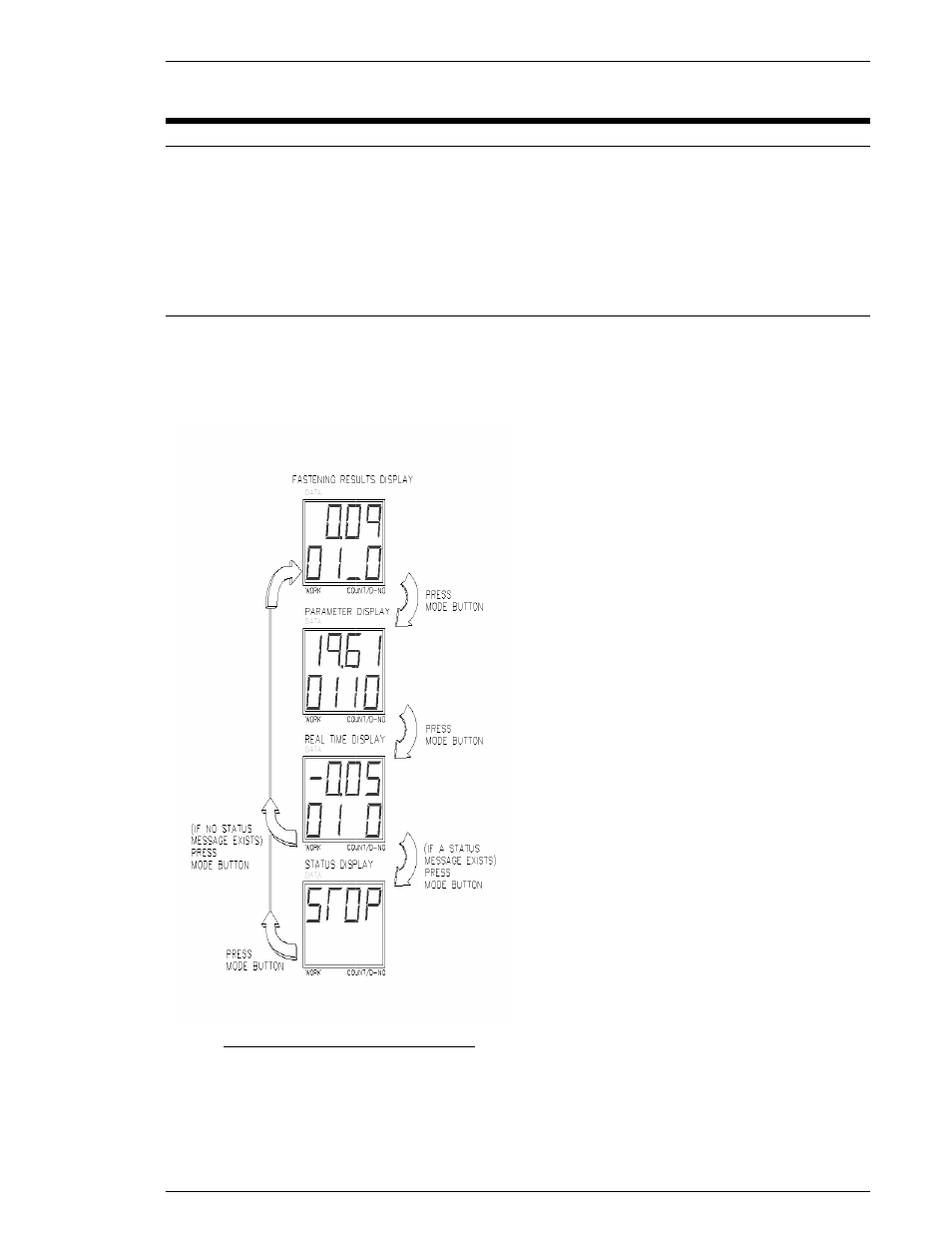
FIG. 7-2-1 Run State Display Modes
The Controller unit is in
Status display mode
indicates if an abnormal conditi
FUSION Operations Manual Chapter 7: System Operations (Rev.2)
Page 7-5
7.2 Run State Modes.
system has two operational states that are controlled by depressing the
“MODE” and “SET” Buttons, on the front of the Controller, simultaneously,
ss input. The operational modes available in the
Run State
are identifie
(after Power-up) the “MODE” and “SET” Buttons have not been pressed simu
and the BYPASS external signal is not active. During the
Run State
mainly shows the results of fastening, abnormalities, preset values, etc.
7.2.1 Display indication modes.
Three modes can be selected while in the
Run State
by pressing the MODE push
] keys to change the D-NO selected, the DATA display contents
varied up or down. The displays will remain blank, and mode selection will be disabled while
the nutrunner is active. (BUSY) If an Abnormal condition occurs, the display will automatica
ly change to the Abnormal (Abn) display mode, displaying the abnormal code and sub
While the Controller Unit is in cycle it will display
the cycle status. The display will indicate where
the cycle is in its fastening sequence. The follo
ing abbreviations will be displaye
play;
In
: Initial Speed
1
E
Fr
: Freerun Speed
2d
SL
: Slowdown Speed
2E
Tq
: Torque Speed
3d
Lo:
Varispeed High Speed
UA:
Varispeed Final Speed
r1
: Reverse
The
Fastening results display mode
when the D-No displays one digit in the right hand
location, and one, two or three dashes in the left
hand location. The results details can be scrolled
by using the
↑↑↑↑
and
↓↓↓↓
keys to change the D
This mode does not function while the
is Busy. Refer to 7.2.3
The
Parameter display mode
D-No displays digits in both the right and left hand
locations. The parameter data can be scrolle
using the
↑↑↑↑
and
↓↓↓↓
keys to change D
to 7.2.4
The
Real time display mode
digit is active in the right hand display only.
When the power is turned on, the default display
mode is the REAL TIME display mode. The di
play contents can be scrolled by using the
↓↓↓↓
keys to change D-NO. Refer to 7.2.2
1 Run State Display Modes
Status display mode
when no digits are displayed. The STATUS display
indicates if an abnormal condition occurs or if an emergency stop has halted the system.
7: System Operations (Rev.2)
depressing the
“MODE” and “SET” Buttons, on the front of the Controller, simultaneously, or by the PLC By-
are identified below. Under
“MODE” and “SET” Buttons have not been pressed simul-
Run State
, the display
mainly shows the results of fastening, abnormalities, preset values, etc.
by pressing the MODE push-button. By
elected, the DATA display contents may be
varied up or down. The displays will remain blank, and mode selection will be disabled while
the nutrunner is active. (BUSY) If an Abnormal condition occurs, the display will automatical-
displaying the abnormal code and sub-code.
Unit is in cycle it will display
the cycle status. The display will indicate where
fastening sequence. The follow-
ing abbreviations will be displayed in the data dis-
: 1
st
Step End,2
nd
next
2d
: 2
nd
Step End
: 2
nd
Step End,3
rd
next
: 3
rd
Step
Fastening results display mode
is active
No displays one digit in the right hand
location, and one, two or three dashes in the left
hand location. The results details can be scrolled
keys to change the D-No.
This mode does not function while the Nutrunner
Parameter display mode
is active when the
No displays digits in both the right and left hand
locations. The parameter data can be scrolled by
keys to change D-No. Refer
Real time display mode
is active when one
digit is active in the right hand display only.
When the power is turned on, the default display
mode is the REAL TIME display mode. The dis-
y contents can be scrolled by using the
↑↑↑↑
and
Refer to 7.2.2
when no digits are displayed. The STATUS display
on occurs or if an emergency stop has halted the system.