FEC FUSIONE-HS-2 User Manual
Page 38
Chapter 3: System Description
Page 3-8
3.2.2 FUSION Tool Control, Displays and Connectors
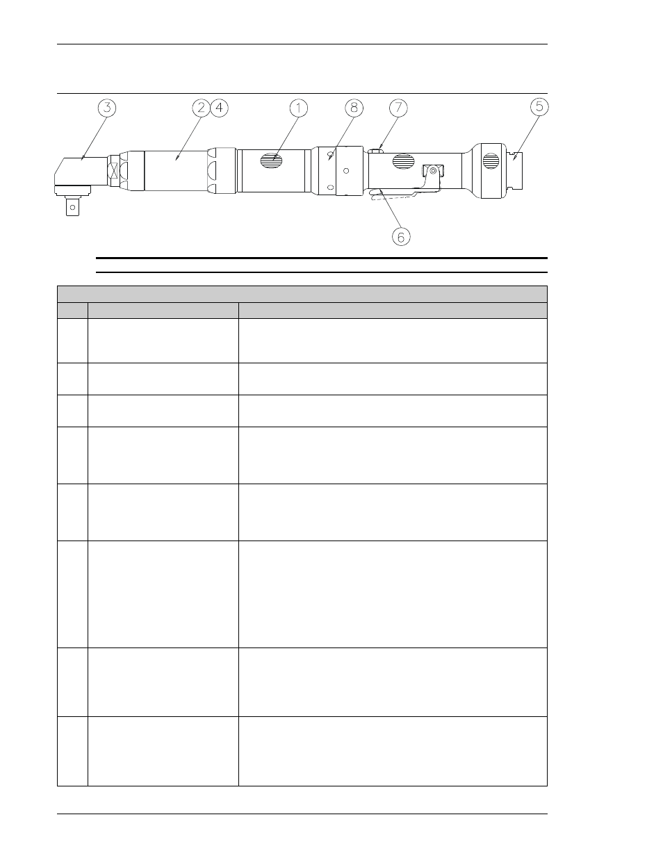
Fig. 3.2.2 Tool Description
TOOL MAJOR COMPONENT IDENTIFICATION
ITEM ITEM AS MARKED ON UNIT
DESCRIPTION
1 MOTOR / RESOLVER
Provides feedback for speed regulation to the Servo Amplifier.
Provides angular rotation monitoring for fastening operation.
Totally enclosed DC permanent magnet motor.
2 TRANSMISSION
Durable planetary gear transmission.
Refer to Chapter 2 for standard tools and gear ratios.
3 ANGLE HEAD
Durable right angle head.
Refer to Chapter 2 for standard tools and gear ratios.
4 TRANSDUCER / PREAMP
Highly accurate strain gage transducer.
Highly durable, compact design minimizes space requirements.
Intelligent transducer design uses an “ID Chip” to verify
integrity of fastening operations.
5 CABLE CONNECTOR
Twist lock single connector for tool cable connection. Twist
lock type connector can be connected and disconnected by
twisting the outside ring 90 degrees clockwise and counter
clockwise respectively.
6 START SWITCH
Variable speed start switch. Depressing the Start switch
partially initiates a manually controlled slow speed start.
Depressing the Start switch fully initiate a fastening cycle as
programmed into the controller. Releasing the Start switch at
any time terminates the fastening operation.
Used to initiate a reverse tool operation when in
Reverse/Backout mode.
7 REVERSE SWITCH
Momentary Reverse selector switch. Depressing the Reverse
selector switch places the tool in the Reverse/Backout mode.
The Accept/Reject LED display on the tool flashes to indicate
Reverse operation selection. Depressing the Reverse selector
switch again, places the tool back in the fastening mode.
8 LED DISPLAY RING
360 degree LED display ring.
Green indicates an accept condition.
Red indicates a Reject condition.
Flashing Red and Green indicate Reverse/Backout mode.
Solid Red and Green during power on for verification.