FEC AFC1200 User Manual
FEC Accessories for electrical
)(& ,QF
4.1
Design and Build Procedure
Review Chapters 1 and 2 prior to designing a System. If the requirements and specifications in
these two (2) Chapters are not addressed, there is a chance of degraded System performance.
WARNING:
FOLLOW LOCKOUT/TAGOUT AND OTHER SAFETY PRECAUTIONS WHEN
CONNECTING AND DISCONNECTING CABLING, WIRING, AND EQUIPMENT.
2.1
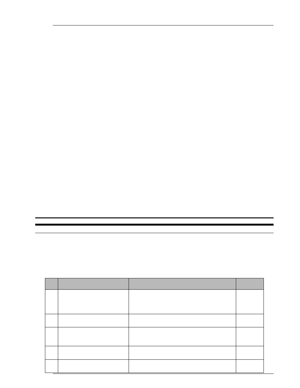
Select an Air Handling Unit applicable to the
environmental conditions (A/C, Heat Exch, etc.)
Select an Air Handling Unit (as
required)
5
4.5
4.6
Circuit protection for the Axis Units should be
separate from the Main Unit.
Select the circuit protectors
4
2.4
2.5.1
Tool motors require specific Servo Amplifiers /
Axis Units. Ensure that each Axis / tool pairing
is compatible.
Select correct Axis Unit(s) for
the tool(s) selected
3
4.4
4.4.3
The spindle arrangement and tool mounting
plate design must meet several specifications.
Design the tool mounting plate/
powerhead/spindle assemblies
2
2.5.1
4.4.1
4.4.2
Required torque range should fall between 50%
and 75% of the tool's capability (full scale
torque). Ensure fastening bolt pattern and tool
mounting patterns are compatible.
Select correct tool size and
configuration
1
Reference
Section
Comments
Description
Step
Chapter 4: System Setup and Wiring
Chapter 4: System Setup and Wiring
Page 4-1