IAI America IA-101-X-USBMW User Manual
Page 208
13. How to Reset an
Absolute Encoder
200
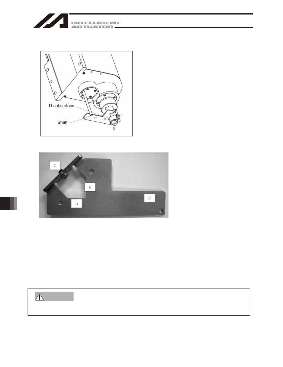
(12) Set the plate and pin constituting the adjustment jig, as shown below, to affix the robot in the reference
posture.
Fig. 14.52 Installing Adjustment Jig
Installation method
[1] Insert the ball-screw spline into the hole in the jig from below.
[2] Cause the D-cut surface of the ball-screw spline to contact the surface a.
[3] Cause the side surface of the ball-screw spline to contact the surface b.
[4] Tighten the screw c to secure the jig onto the ball-screw spline.
* At this time, confirm that the adjustment jig is vertical to the ball-screw spline and that the D-cut
surface and surface a are firmly in contact.
* Applicable screw: Hexagonal socket head setscrew M5
* Tightening torque: 20 [N-cm] (reference)
[5] Insert the supplied shaft into the hole in the ZR unit.
* Exercise caution because the shaft will come off if the hand is released.
[6] Turn the ball-screw spline until the supplied shaft contacts lightly with the surface d of the jig.
x
Always press the EMERGENCY STOP switch before setting an adjustment jig. Failure to do so may
cause the actuator to malfunction and result in a serious accident.
Warning