IAI America IA-101-X-USBMW User Manual
Page 157
10. Coordinate System Definition Data Edit W
indow
149
ޓ
ޓ
ޓ
;D
:D 㧙
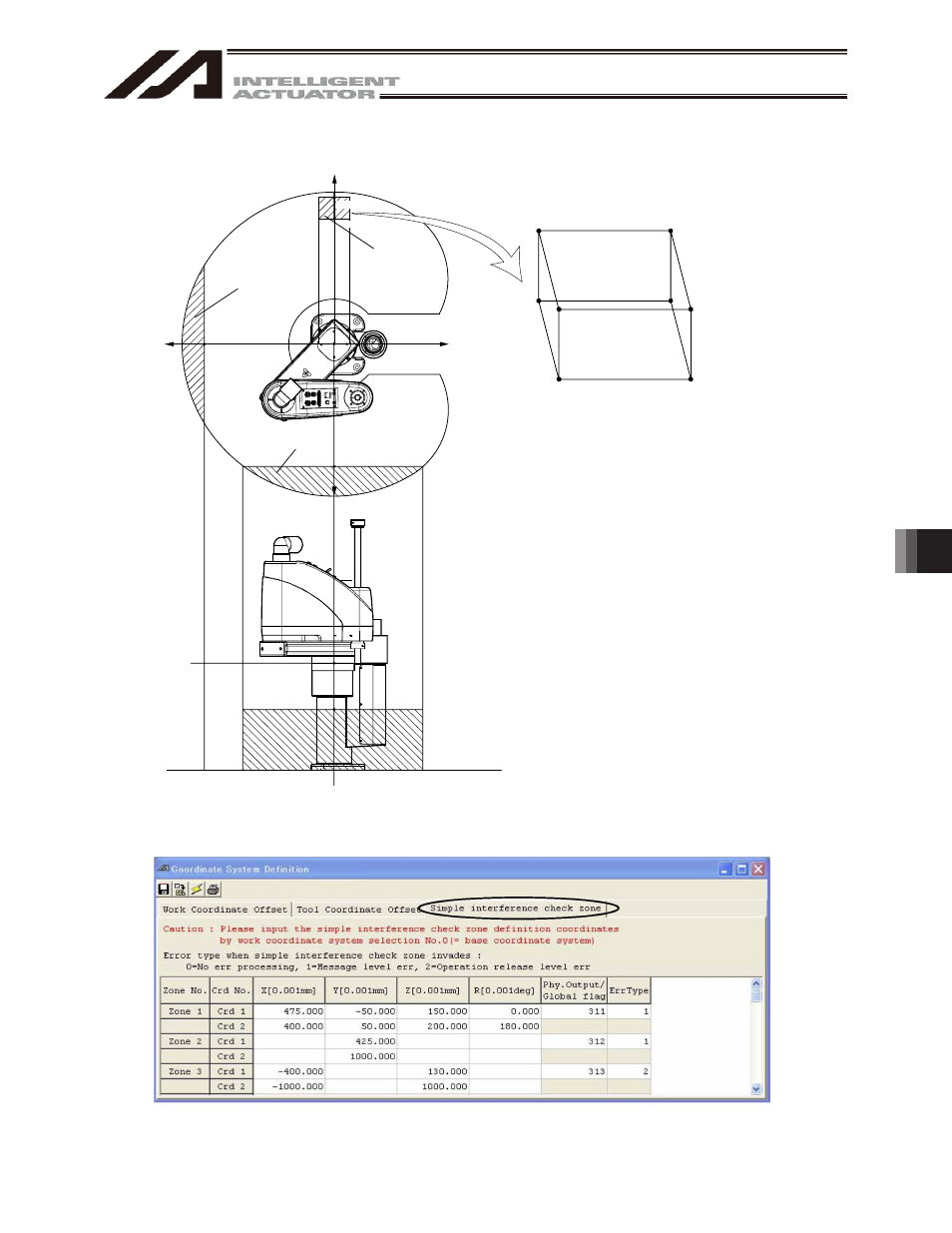
㧗:D 㧗;D 㧙;D :D :D # $ % & ' ( ) * [1] Set simple interference check zone No. 1 as a rectangular solid. A: Xb=475, Yb=-50, Zb=150, Rb=0 G: Xb=400, Yb=50, Zb=200, Rb=180 If Rb is outside the 0 to 180°range, entry into this rectangular solid is not detected. [2] Set simple interference check zone No. 2 as an area where Yb is 425 mm or more. [3] Set simple interference check zone No. 3 as an area where Xb is -400 mm or less and Zb is 130 mm or more. Simple interference check zone No. 2 Simple interference check zone No. 3 Simple interference check zone No. 1 Setting example of simple interference check zones Define simple interference check zones No. 1, No. 2 and No. 3 as shown below: Shown below is the data edit screen to define simple interference check zones when simple interference check zones No. 1, No. 2 and No. 3 are set respectively. Fig. 10.15 Simple Interference Check Zone Definition Coordinates Setting Screen