IAI America IA-101-X-USBMW User Manual
Page 154
10. Coordinate System Definition Data Edit W
indow
146
(2) Positioning based on tool coordinate system offsets
Perform positioning after selecting a desired tool coordinate system.
Use the SLTL instruction to select a desired tool coordinate system No. in the SEL program.
Once set, the tool coordinate system selection No. will remain effective after the program ends, and even
after the power is reconnected if the system memory backup battery is installed.
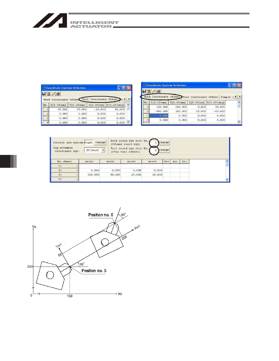
[1] When performing PTP positioning of the tool end in tool coordinate system No. 1 to position No. 5
and No. 6 in work coordinate system No. 1:
Fig. 10.9 Tool Coordinate System Offset Setting Screen Fig. 10.10 Work Coordinate System Offset Setting Screen
Fig. 10.11 Position Data Screen:
Work Coordinate System No. 1 and Tool Coordinate System No. 1 Setting
Sample program
:
:
SLWK 1 Select work coordinate system No. 1.
SLTL 1 Select tool coordinate system No. 1.
PTPR
Specify right arm as the PTP target
arm.
MOVP 5 Move to position No. 5.
MOVP 6 Move to position No. 6.
:
:
:
The Z-axis position at the tool end is as follows:
Position No. 5 Zb = 0
Position No. 6 Zb = 20
A top view is shown at the left.