IAI America IA-101-X-USBMW User Manual
Page 155
10. Coordinate System Definition Data Edit W
indow
147
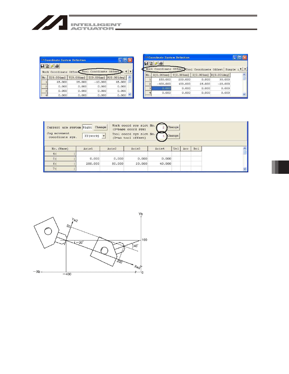
[2] When performing PTP positioning of the tool end in tool coordinate system No. 1 to position No. 5
and No. 6 in work coordinate system No. 2:
Fig. 10.12 Tool Coordinate System Offset
Setting Screen
Fig. 10.13 Work Coordinate System Offset
Setting Screen
Fig. 10.14 Position Data Screen:
Work Coordinate System No. 2 and Tool Coordinate System No. 1 Setting
Sample program
:
:
:
SLWK 2 Select work coordinate system No. 2.
SLTL 1 Select tool coordinate system No. 1.
PTPR
Specify right arm as the PTP target arm.
MOVP 5 Move to position No. 5.
MOVP 6 Move to position No. 6.
:
:
:
The Z-axis position at the tool end is as follows:
Position No. 5 Zb = 25
Position No. 6 Zb = 45
This manual is related to the following products: