4 expansion or reduction of physical memory, 4 expansion or reduction of physical memory -29 – Hitachi GR2000 Series User Manual
Page 291
Maintenance Procedure
GR2K-GA-0015
8-29
Ver. 07-02
system is standby. Refer to the Figure 8-27 of the result of
show router
command.
> show router [CR]
The above is the procedure for replacing the standby system BCU or the
standby system CPU fan with the power supply on.
8.4.4
Expansion or Reduction of Physical Memory
The physical memory units for BCUs and RPs can be expanded on the standby side
of a duplex router while operating. This subsection provides examples of typical
concurrent physical memory upgrade.
(1) Concurrent Upgrade of BCU Memory while Power is On
To expand the BCU memory, the BCU (RM-CPU board) must be removed from the
router. Therefore, memory expansion on the active side cannot be performed during
operation. To expand the memory of both BCUs on a duplex router, expand the
memory on the standby side, and then swap the system and expand the memory on
the new standby side.
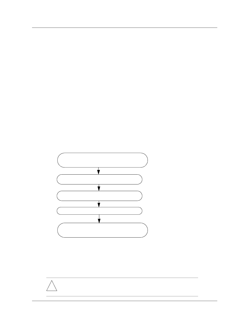
Figure 8-32 shows the steps for expanding the standby BCU memory while the power
is on. Details of each step follow the figure.
Figure 8-32 Procedure for Replacing Standby BCU
Step 1.
Configure-off the standby BCU:
See Subsection 8.3.1, item 1 Step 1.
Step 2.
Remove the standby BCU:
See Subsection 8.3.1, item 1 Step 2.
!
WARNING: Hazardous voltage. Can cause death or severe injury. Removing/adding
component while power is on must be conducted by trained and qualified
engineer or maintenance personnel.
Configure-off the standby BCU by executing the
close standby
command from the active side.
Step 1
Remove the standby BCU
Expand memory units on the removed standby
BCU (RM-CPU board).
Install the standby BCU again.
Configure-on the standby BCU by executing the
free
standby
command from the active side.
Step 2
Step 3
Step 4
Step 5