Figure 8-9. result of s – Hitachi GR2000 Series User Manual
Page 272
Hitachi Gigabit Router GR2000 Series Enhanced Version Operations - Device Management Overview
8-10
GR2K-GA-0015
Ver. 07-02
Step 1.
Configure-off the standby BCU.
From the device management terminal connected to the active side of the
router, enter
show router
command and confirm the status of the standby
system.
> show router [CR]
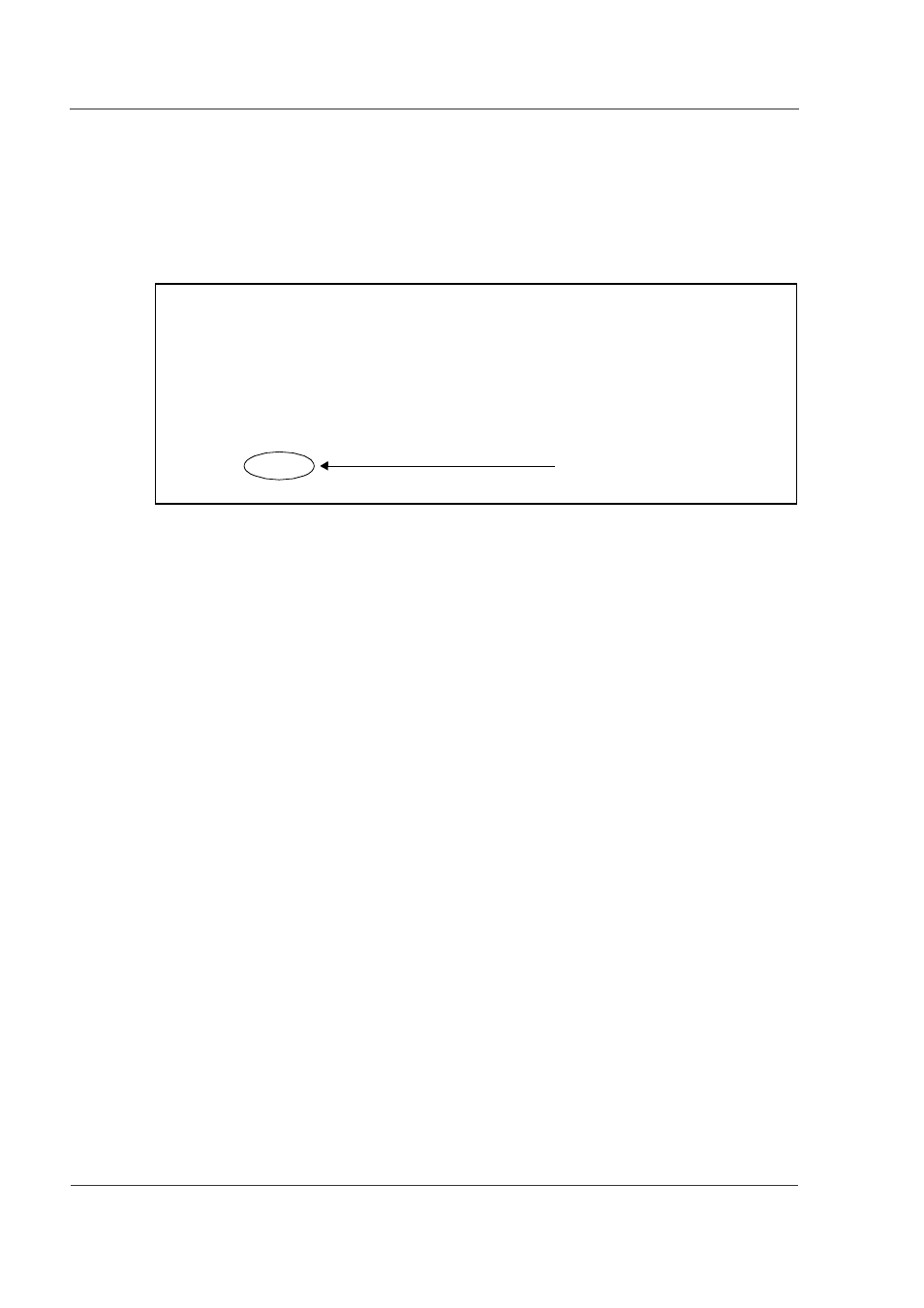
Figure 8-9 shows the command execution result, where “rm0” is the active
system and “rm1” is the standby system.
Figure 8-9 Result of show router Command
(a) When the standby BCU turns out to be failing:
When the standby BCU fails, its status becomes “fault.” In this case, from
the operation terminal connected to the operation system, enter the
command shown below.
> close standby [CR]
After entering this command, remove the standby BCU in accordance with
Step 2 shown below.
(b) When swapping the CPU fan:
When the CPU fan is to be swapped, confirm that the status of the standby
BCU is other than “fault.” Enter the command shown below.
> close standby [CR]
Make sure that the STATUS LED of the standby BCU’s RM-I/O board is lit
yellow. Then, remove the standby BCU in accordance with Step 2 shown
below.
> show router
router: GR2000 S-9181-11 01-01 [ROUTE-OS] , standard model
node : name=System Name
contact=Contact Address
locate=Location
: : : : : :
rm0 : active
rm : HN-F9533-5M3 [BCU-M300] 0000
boot : 10/10 20:10:34 , power on , 0 times restart
: : : : : :
rm1 : fault
: : : : : :
Status of the standby system.