Hitachi GR2000 Series User Manual
Page 273
Maintenance Procedure
GR2K-GA-0015
8-11
Ver. 07-02
Step 2.
Remove the standby BCU.
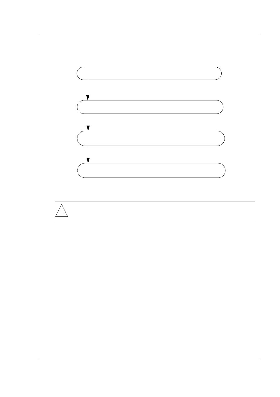
Figure 8-10 shows the procedures for removing the standby BCU. Removing
the standby BCU must be performed in the order of RM-I/O, RM-CPU, and
CSW (GR2000-20H only).
Figure 8-10 Procedure for Removal of Standby BCU
!
WARNING: Hazardous voltage. Can cause death or severe injury. Removing/adding component
while power is on must be conducted by trained and qualified engineer or
maintenance personnel.
Remove the MC card installed on the standby BCU RM-I/O board.
Remove the RM-I/O board from the standby BCU.
Note: If the MC card is removed during MC access, it might fail;
check the MC card access LED.
Remove the RM-I/O board from the standby BCU.
Remove the CSW from the standby BCU.
Note:
The last step is required only for the GR2000-20H.