4 removal/addition of boards and physical memory, 1 removal of boards while power is on, 1 removal of boards while power is on -21 – Hitachi GR2000 Series User Manual
Page 283: Figure 8-22. steps for removal of standby bcu -21
Maintenance Procedure
GR2K-GA-0015
8-21
Ver. 07-02
8.4
Removal/Addition of Boards and Physical Memory
8.4.1
Removal of Boards while Power is On
This section explains the procedure for removing any board encountering a failure in
the router’s BCU, RP, or NIF. It is also not possible to remove or add models
GR2000-1B, GR2000-2B, GR2000-2B+ and GR2000-BH while the power supply is
turned on. Be sure to turn the power supply off before adding or removing either
model [ROUTE-OS6B].
(1)
Removal of Standby BCU while Power is On
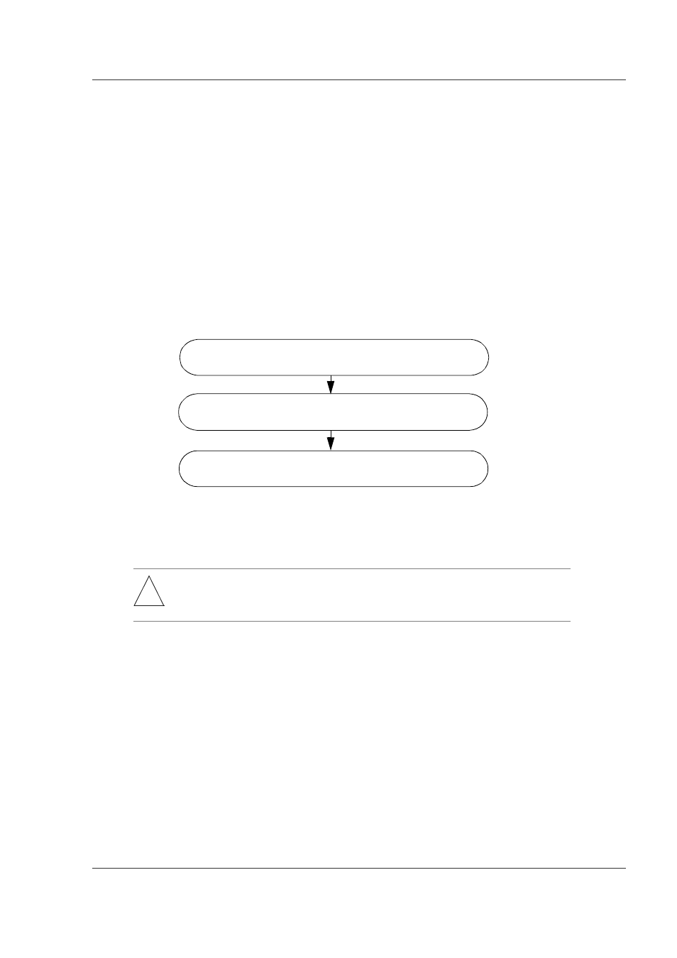
Figure 8-22 shows the steps for removing the standby BCU while the power is on.
Details of each step follow the figure.
Figure 8-22 Steps for Removal of Standby BCU
Step 1.
Configure-off the standby BCU: See Subsection 8.3.1, item 1, Step 1.
Step 2.
Remove the standby BCU: See Subsection 8.3.1, item 2, Step 2.
Step 3.
Change the operation mode of the device if necessary:
When the standby BCU is removed from a router operating as a duplex
(redundant) system and three minutes elapse, the active BCU detects a
failure and outputs an error log. If you want to suppress such error
detection until the new standby BCU is installed, or to use the router
thereafter as a simplex (non-redundant) system, enter
set mode
command
as shown below after changing the user level to administrator.
#set mode simplex [Enter]
Confirm that the 7-segment LED for duplex mode is turned off and that the
operation mode is simplex. The latter can be confirmed with the
information
command. Figure 8-23 shows the results of the
show router
command.
!
WARNING: Hazardous voltage. Can cause death or severe injury. Removing/adding
component while power is on must be conducted by trained and qualified
engineer or maintenance personnel.
Configure-off the standby BCU by entering the
close standby
command from the active side.
Remove the standby BCU.
If necessary, change the operation mode of the device by
executing the set mode command from the active side.
Step 1
Step 2
Step 3