Hitachi GR2000 Series User Manual
Page 281
Maintenance Procedure
GR2K-GA-0015
8-19
Ver. 07-02
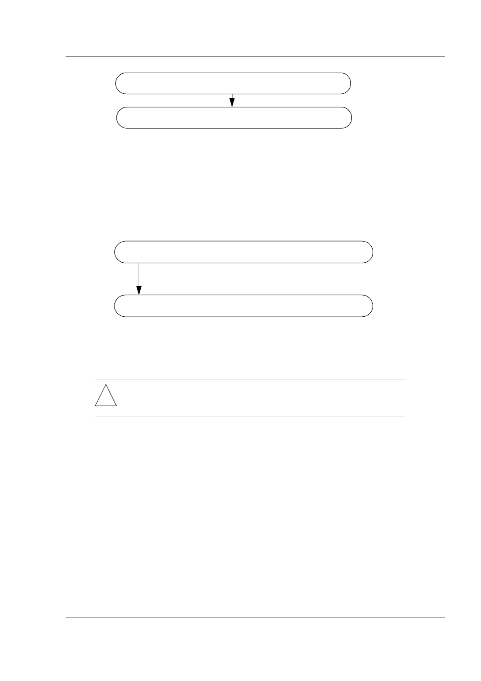
Figure 8-19 Procedure for Removal of BCU
Step 3.
Install a new BCU:
Figure 8-20 shows the procedures for installing a new BCU. There is no
particular order for installing the RM-I/O or RM-CPU board while the power
is off.
Figure 8-20 Procedure for Installation of Standby BCU
Step 4.
Turn the power for the device on.
Step 5.
Register the CPU fan swap date and restart the device.
See section 4.3.1(1) Step 4.
Step 6.
Ensure the operation status of the standby BCU.
When you have finished the steps up to 5 and want to use the new BCU as
the standby system, enter the
show router
command as shown below from
the device management terminal connected to the active system. Confirm
that the operation status of the standby BCU is standby.
> show router [CR]
Figure 8-21 shows the result of
show router
command.
!
WARNING: If the device is configured with power supply redundancy, the device has
multiple input power sources. In such configuration, be sure to turn on all
power sources in accordance with the GR2000 Installation Guide.
Remove the MC card installed on the BCU RM-I/O board.
Remove the BCU.
(Note)
There is no particular order for removing the RM-I/O or RM-CPU board while the power is off.
Load the MS on the new BCU’s RM-CPU board.
Note: Insert the MS64 and MS128 into the RM-CPU board
memory slot to equal the amount installed before swapping.
Install the BCU.
Note: Do not install the MC card removed in Step 2 yet.