Figure 8-23 sh – Hitachi GR2000 Series User Manual
Page 284
Hitachi Gigabit Router GR2000 Series Enhanced Version Operations - Device Management Overview
8-22
GR2K-GA-0015
Ver. 07-02
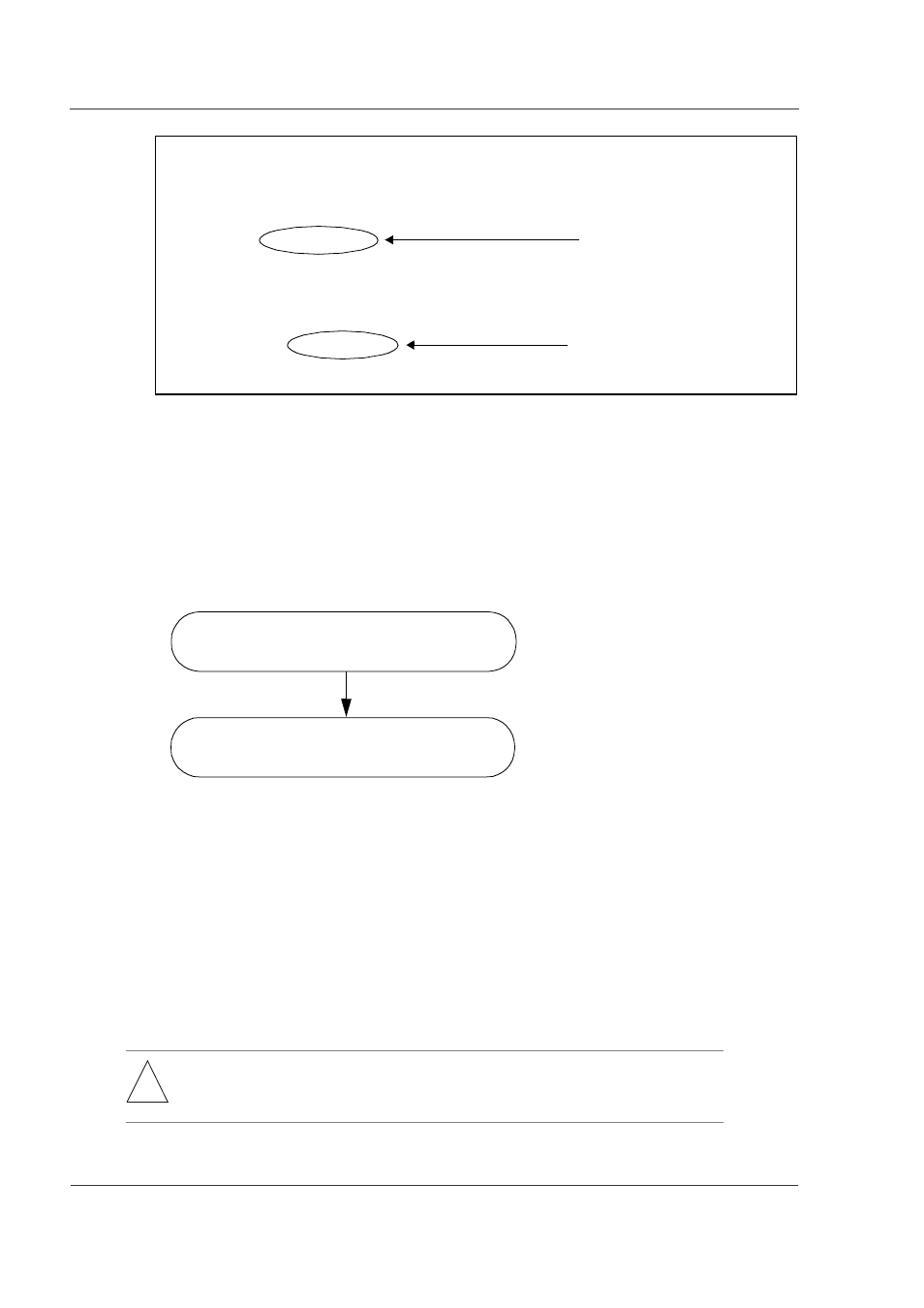
Figure 8-23 Result of show router Command
The above is the procedure for removing the standby system BCU while the power
supply is on.
(2) Removal of RP while Power is On
Figure 8-24 shows the steps for removing the RP while the power is on. Details of
each step follow the figure.
Figure 8-24 Procedure for Removing RP
Step 1.
Cause the target RP to stop operation:
Cause the target RP to stop operation by entering the following command
from the device management terminal. In this step, all NIFs under the
control of the subject RP will also be stopped, even though any of such NIFs
are operating.
close [-f] rp
Step 2.
Remove the target RP board:
Remove the target RP board after confirming that its STATUS LED is lit
yellow. Remove the NIF if necessary. For the removal instructions, see the
GR2000 Installation Guide.
!
WARNING: Hazardous voltage. Can cause death or severe injury. Removing/adding
component while power is on must be conducted by trained and qualified
engineer or maintenance personnel.
> show router
router: GR2000 S-9181-11 01-01 [ROUTE-OS] , standard model
node : name=System Name
contact=Contact Address
locate=Location
node info: simplex mode
: : : : : :
rm0 : active
rm : HN-F9533-5M3 [BCU-M300] 0000
boot : 10/10 20:10:34 , power on , 0 times restart
: : : : : :
rm1 : disconnect
rp0 unused
: : : : : :
Operation mode is simplex.
Standby system is not connected.
Cause the target RP to stop operation.
Remove the target RP board.
Step 1
Step 2