Hitachi GR2000 Series User Manual
Page 287
Maintenance Procedure
GR2K-GA-0015
8-25
Ver. 07-02
(a) When setting the priority MC card slot upon activation of the standby
system
If MC cards are installed in both MC card slots 0 and 1, MC card slot 0 is
set to be activated with priority when in the initial state after BCU
replacement. Therefore, if you are operating with the setting that activates
MC card slot 1 with priority using the
set mode
command prior to standby
BCU replacement and it is desired to continue activating MC slot 1 with
priority as before after the replacement of the standby BCU, re-execute the
setting by the
set node
command indicated below after switching to the
router manager mode from the operating terminal connected to the working
system.
#set mode standby slot1 reload [CR]
After setting the priority MC card slot at the time of standby system
activation, reactivate the standby system by the
reload
command indicated
below from the operating terminal connected to the working system. This
command need not be executed by the router manager.
> reload dump-image -f standby [CR]
After reactivation of the standby system, and want to use the new BCU as
the standby system, enter
show router
command as shown below from the
device management terminal connected to the active system. Confirm that
the operation mode is duplex mode and the operation status of the standby
system is standby. Refer to the Figure 8-27 of the result of
show router
command
> show router [CR]
The above is the procedure for replacing the standby system BCU or the
standby system CPU fan with the power supply on.
(2) Concurrent Upgrade of RPs
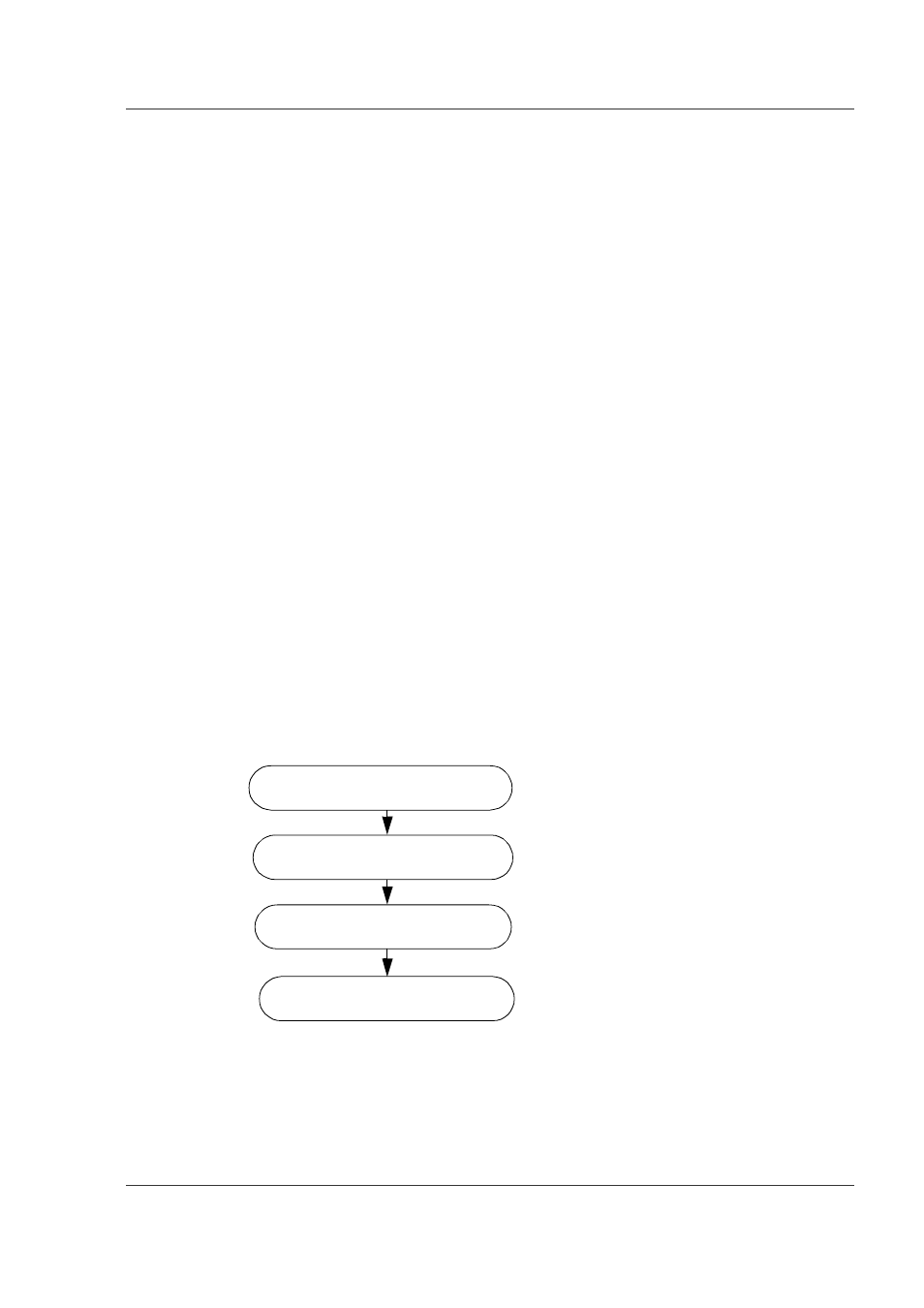
Figure 8-28 shows the steps for upgrading of the RPs while the power is on. Details
of each step follow the figure.
Figure 8-28 Steps for Concurrent Upgrade of RPs
Insert RPs
Insert NIFs (as necessary)
Start the operation of the RPs
Define the configuration
information (as necessary).
Step 1
Step 2
Step 3
Step 4