3 tmpr3912/22u and s1d13704/5 interface, 1 hardware connections, Figure 31: s1d13704 to tmpr3912/22u interface – Epson S1D13705 User Manual
Page 524
Page 10
EPSON Research and Development
Vancouver Design Center
S5U13704/5 - TMPR3912/22U CPU Module
X00A-G-004-02
Issue Date: 01/03/07
3 TMPR3912/22U and S1D13704/5 Interface
3.1 Hardware Connections
The S1D13704/5 occupies the TMPR3912/22U’s PC Card slot #1. Therefore, this slot
cannot be used for other devices on the main board. The Generic # 2 bus mode of the
S1D13704/5 is used to interface to this PC Card slot #1.
The S1D13704/5 is interfaced to the TMPR3912/22U with minimal glue logic. Since the
address bus of the TMPR3912/22U is multiplexed, it is demultiplexed using an advanced
CMOS latch (74ACT373) to obtain the higher address bits needed for the S1D13704/5.
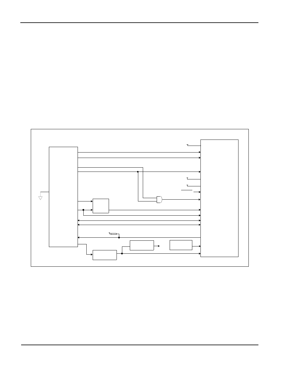
The following diagram demonstrates the implementation of the interface.
Figure 3-1: S1D13704 to TMPR3912/22U Interface
WE10#
RD#
DB[7:0]
WAIT#
BUSCLK
S1D13704
RESET#
AB[15:13]
D[31:24]
CARD1WAIT*
A[12:0]
TMPR3912/22U
10K pull-up
WE1#
CARD1CSL*
CARD1CSH*
Latch
ALE
System RESET
WE*
RD*
BS#
RD/WR#
3.3V
3.3V
ENDIAN
DB[15:8]
D[23:16]
AB[12:0]
3.3V
DCLKOUT
CS#
CLKI
or...
Clock divider
IO V
DD
, CORE V
DD
+3.3V
/ 2
Clock divider
/ 2
Oscillator