Table 23: jumper settings – Epson S1D13705 User Manual
Page 297
Epson Research and Development
Page 9
Vancouver Design Center
S5U13705B00C Rev. 1.0 ISA Bus Evaluation Board User Manual
S1D13705
Issue Date: 01/02/13
X27A-G-005-03
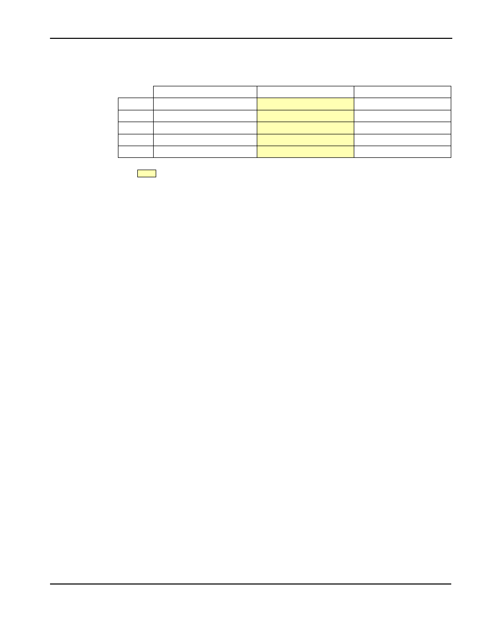
Table 2-3: Jumper Settings
Description
1-2
2-3
JP1
IOVDD Selection
5.0V IOVDD
3.3V IOVDD
JP2
RD/WR# Signal Selection
Pulled up to IOVDD
No Connection
JP3
BS# Signal Selection
Pulled up to IOVDD
No Connection
JP4
LCD Panel Voltage Selection
5V LCD Panel
3.3V LCD Panel
JP6
LCDPWR polarity
Active low (‘LCDPWR#’)
Active high (‘LCDPWR’)
= recommended settings (JP1 through JP3 configured for ISA bus support)